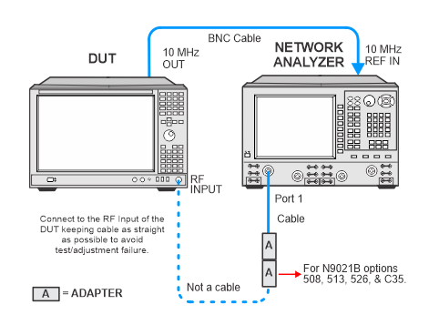
In the following setups, cables are designated as solid lines and direct connections are designated as dashed lines.
UXA — N9040B with frequency options above 526
And with options:
MPB
The goal of this adjustment is to generate corrections for the IF band shape. Option MPB is necessary is because the YTF is a tunable bandpass filter with a nominal bandwidth of 30 MHz to 50 MHz. The bandwidth of the YTF will band limit the IF Frequency Response. Bands 0, 1, 2, 3, 4, 5, 6 are adjusted.
In this adjustment a –10.00 dBm signal is applied to the signal analyzer. A reference amplitude is taken at the IF Center Frequency. The Source Frequency is then changed to a series of offset frequencies within the span of the IF. At each offset frequency the input amplitude is maintained at –10.00 dBm, and the signal amplitude is measured by the signal analyzer. The offset amplitude is subtracted from the reference amplitude. The resulting envelope created by all the offset amplitudes is the uncorrected IF Frequency Response.
Click here for troubleshooting.
|
Test Equipment |
Recommended Model Number |
|---|---|
|
Network Analyzer1, 2 |
N5247B
|
|
Cable, BNC (m) to BNC (m) |
8120-1840 |
|
Cable, 2.4 mm (f) to 2.4 mm (m) |
8121-2065 (or equivalent) |
|
Adapter, 2.4 mm (f) to 2.4 mm (f) |
11900B (or equivalent) |
|
Adapter, Type-N (m) to 2.4 mm (m)
|
11903A |
|
Adapter, 2.4 mm (m) to 3.5 mm (f)
|
11901C |
|
The network analyzer used in this adjustment must be calibrated prior to running the adjustment. The calibration will need to be repeated once every three days or if the connectors or cables have been disturbed. If it's been within the three day time frame and the connectors and cables have not been disturbed, then the network analyzer calibration is not necessary and you may proceed with the adjustment.
For a list of required equipment and calibration instructions to perform the network analyzer calibration, refer to Network Analyzer Freq Sweep Calibration.
|
|
In the following setups, cables are designated as solid lines and direct connections are designated as dashed lines. |