Channel Match Option BBA Performance Test

This test applies to the following models with Option BBA:

The BBIQ Verification tests rely on the BBIQ Front Panel Alignment being run within 8 hours of running a verification test. If the alignment timestamp is greater than 8 hours from the current time, TME will run the BBIQ alignment. If the time difference between the DUT and the TME station clock is more than 8 hours, then TME will get stuck in an endless BBIQ alignment loop. To prevent this from happening, the DUT clock should be set to the local time. At the end of the adjustment cycle, set the DUT clock back to the customer's local time.

The Baseband IQ (BBIQ) hardware is a separate measurement path from the signal analyzer RF path. The BBIQ path is controlled through the IQ Analyzer Mode. The BBIQ hardware has four different input ports (or channels):

  • I (unbalanced)

  • I-Bar (balanced)

  • Q (unbalanced)

  • Q-Bar (balanced)

Each input port has 4 different amplitude ranges:

  • 1 Volt Peak (+10 dBm)

  • 0.5 Volts Peak (+4 dBm)

  • 0.25 Volts Peak (-2 dBm)

  • 0.125 Volts Peak (-8 dBm)

Each input has two impedance choices: 50 Ohm and 1 Meg Ohm. There are potentially 32 different Input/Range/Impedance test variants that need to be tested.

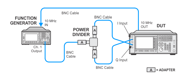
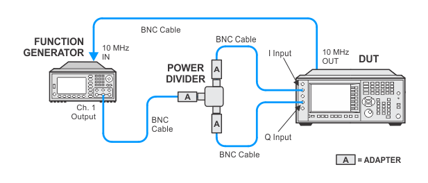
Channel Match is defined as the Amplitude and Phase difference between the I and Q channels. In this test a sine wave is input to a splitter, and the splitter outputs are connected to the I and Q inputs. The signal is digitized and then an FFT is performed on the data. The I and Q inputs are swapped in order to eliminate the splitter tracking errors. Amplitude and Phase are compared between the I and Q channels for each frequency.

This test will depend on the BBIQ IQ Cable Cal. The IQ Cable Cal is a frequency response calibration that is done manually on the signal analyzer. If the time since a IQ Cable Cal has been performed is more than 8 hours, the user will be prompted to perform an IQ Cable Cal.

Click here for troubleshooting.

Required Test Equipment

Test Equipment

Recommended Model Number

Function Generator

33622A

Power Divider

11636B 

BNC Cable
(4 ft, 2 required)

8120-1840

BNC Cable
(9 inch, 2 required)

10502A 

BNC (f) to 3.5 mm (m) adapter
(3 required)

1250-1200

Connection Setups

In the following setups, cables are designated as solid lines and direct connections are designated as dashed lines.

Channel Match Test Setup


Channel Match (reverse connection) Test Setup