Installation
Before You Start
Installing Over Previous Versions
Please see the Readme.txt for information on the compatibility of this
package with previous versions of the application and the Test Management
Environment.
|

|
TME applications E.01.00 and later cannot be installed over older TME
applications (A.xx, C.xx, or D.xx) or on top of TME versions prior to
E.01.00. You must remove TME and all applications from the PC before installing
the latest TME and this application. Please see the Installation page of the Getting Started section in the TME Help for details
of how to remove pre-E.01.00 versions of TME and its applications.
|
Separation of TME from Applications
Keysight TME is no longer packaged and installed with
TME applications. TME must be installed separately. Once TME is installed
on the target PC, the applications can then be installed.
Please see the TME help system and Readme for information
on installing the Keysight Test Management Environment. Both can be found at www.cal.software.keysight.com
System Requirements
Please see the Readme.txt for minimum system requirements to run this
application.
There are two ways to install TME and its applications:
-
Network
Installations — Equipment and test data information is stored in a
central location (the TME Server). This data is shared among a set of
TME Clients. Multiple test stations can then have access to this central
information.
-
Local Installations — Everything is installed on one PC
Network Installation
In a network installation, order information is stored centrally and
can be accessed by any TME client in the network. This allows you to combine
data from tests that were run on multiple stations into a single report.
Equipment data and order information are also accessible from any station.
To set up a new TME network, please see the instructions in the TME
help system.
|
|
-
The
installation of the application network data must take place on the same
PC that installed the TME network data.
-
If TME is setup as a network installation, the application will automatically
be setup as a network on that machine when the installation is executed.
The application server must be installed before any clients can be installed.
-
TME client must also be installed on all machines intending to run this
application as clients of the network.
|
To install an application on a network follow the following steps:
-
Find the PC where the TME network was installed (shows
“TME Server” in Add/Remove Programs or Programs and Features depending on the OS).
-
Run Setup.exe for the application on that PC. This will
install all networked components for that application.
-
Install application clients:
Or
\\FileServer\Test
Management Environment\Install\(AppName)\(AppName)ClientSetup.exe
|
|
The
client setup must be run from this location. It should not be moved or
renamed.
|
Local Installation
TME must be installed on the target PC before the application
installation can occur.
On a local installation, all application data is stored
on the target PC. Once TME has been installed as a local installation
the application installation will automatically install locally when executed.
Order information, test results, and equipment data will not be shared
with other users.
Uninstallation
|

|
If you uninstall TME completely or uninstall any TME application,
you will lose the data associated with those applications. Create any
reports needed and save them as PDF files before you perform any uninstallation
of that product.
|
-
To uninstall previous versions of TME, please see Installing
over Previous Versions.
-
To uninstall TME or any TME application, select that package
from Add/Remove Programs or Programs and Features depending on the OS on the Control Panel.
Uninstall of Nework Install
To uninstall an application client, select that package
from Add/Remove Programs or Programs and Features depending on the OS on the Control Panel and click Remove.
|
|
Data
will not be lost if only a client is uninstalled. Other clients will still
have access to the data in the network.
|
To uninstall an application server:
-
Follow the directions above to uninstall all application
clients.
-
Once all application clients have been uninstalled,
uninstall the application server from the PC where the server installation
was performed.
-
Select the application server from package
from Add/Remove Programs or Programs and Features depending on the OS on the Control Panel and click Remove.
Uninstall of Local Install
To uninstall an application local installation, select that package
from package
from Add/Remove Programs or Programs and Features depending on the OS on the Control Panel on the Control Panel and click Remove.

Connecting GPIB Test Instruments
This section describes the preparation of the instruments
used by the test software at a given test station. The test software does
not check instruments for proper operation on the GPIB bus before attempting
to perform tests.
The typical GPIB address configuration for a test station is:
|
Spectrum Analyzer
|
18
|
|
|
Power Meter
|
13
|
|
|
Frequency
Counter
|
3
|
|
|
Pulse Generator Schwarzbeck IGUU 2918
|
3
|
This is a fixed addressed. The GPIB address of the frequency counter may need to be changed to avoid conflicts. See below for important information about possible GPIB connection issues with the IGUU 2918.
|
|
Source
|
19
|
|
|
Network Analyzer
|
16
|
|
|
DVM
|
22
|
|
|
Function Generator
|
10
|
|
|
Pulse Generator Schwarzbeck IGUU 2916
|
10
|
This is a fixed addressed. The GPIB address of the function generator may need to be changed to avoid conflicts.
|
|
Oscilloscope
|
4
|
|
Known issue with IGUU 2918 and Keysight IO Library
There is a known issue with certain versions of the Keysight IO Library not recognizing the Schwarzbeck IGUU 2918 pulse generator and therefore causing a GPIB connection failure.
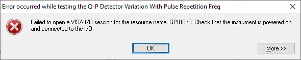
Note that this issue does not occur with the IGUU 2916.
This issue will be addressed in a future release of IO Libraries. Until then, there are two work-around methods should you encounter a connection error.
Solution 1: Install the last Agilent-branded version of IO Libraries
The last Agilent-branded version of IO Libraries (version 16.3.17914.4) will recognize the IGUU 2918. This version can be downloaded from the Keysight IO Libraries website:
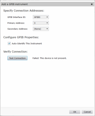
Solution 2: Manually add the IGUU 2918
Manually adding the IGUU 2918 in Keysight Connection Expert will allow the IGUU 2918 to communicate.
-
Open Keysight Connection Expert and click on the +Add button and select GPIB instrument.
-
In the next window, select:
- GPIB Interface ID: GPIBO
-
Primary Address: 3
Don't worry if the Test Connection function fails.
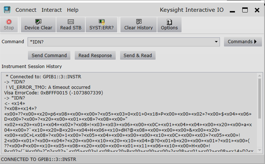
-
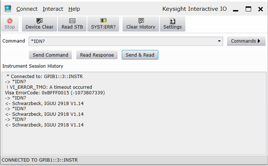
Do a *IDN? query.
- In Connection Expert, open Interactive IO.
-
From the Commands tab, select *IDN?
-
If the command times out or returns a , repeat it. You many need to repeat the command several times before the command will return .
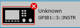
Although Connection Expert may not show the correct model or serial number for the IGUU 2918, and it may as not being connected, you should at this point be able to run tests without any errors.
If neither of these solutions work, please contact TME Customer support: tmen7800asupport@keysight.com
Initialization Failure
If the station cannot connect to the signal analyzer (see error message below), then the signal analyzer may be configured as a controller. To disable this function, press: System g I/O Config g GPIB g GPIB Controller. Select: Disabled

It is recommended that the operator follow the steps below to manually
check for proper connection of the GPIB devices before performing tests
on a newly connected test station.
-
Note the GPIB address of each
instrument associated with the test station/test plan defined earlier.
-
Connect a power cord to each
instrument, and then connect each instrument to the computer serving as
the GPIB controller.
-
Power up all the instruments
on the GPIB bus.
-
Check each GPIB instrument for proper communication
over the bus and the required "" options. Follow the
process described in "Checking GPIB Bus Devices" below.
Checking GPIB instruments
|

|
When checking the basic operation of each instrument or when checking
for detectable options on a given instrument, you may need to look up
the actual command for retrieving the identification string before performing
these steps.
|
-
Start the Keysight Connection Expert from the task bar or access it through Start > All Programs > Keysight Connection Expert.
-
Check for all expected GPIB devices. Verify that all expected GPIB devices are shown in the left window. If a device is missing, correct the problem and re-scan for connected instruments.
-
Check all GPIB device addresses:
-
Verify that no two GPIB addresses are the same.
-
Follow the process described in the user manual
for the device if an address needs to be changed. The following numbers
are reserved and are not available for GPIB addresses: 0, 1, 21, 31.
-
After changing the address of the device, go to
the Administration area, highlight the device icon, and enter the correct
GPIB address into the Address field.
-
Check for basic operation of each GPIB device:
|
|
If an instrument does not support SCPI, refer to the user guide for
the product to learn more about checking the basic operation of its GPIB.
|
-
Select a GPIB device.
-
Select the Interactive
I/O from the right window.
-
The command window should be pre-populated with the *IDN? query. You can also select from the Commands > drop-down menu, or simply type *IDN? in the command window.
-
Select Send & Read.
-
Verify that the expected model number is contained
in the response text string.
-
Check for on a given device:
|
|
This does not work on a power meter.
|
-
Select a GPIB device to highlight it.
-
Select the Interactive
I/O from the right window.
-
Type *OPT?
in the command window.
-
Select Send & Read.
Aborting from Performance Tests or
Adjustments
|
|
These steps should not be performed while the adjustments are writing
calibration files to the instrument.
|
Some performance tests or adjustments use very long sweep times, which
cause TME to not respond to abort requests. The following steps will allow
you to abort from these tests or adjustments:
-
Click Abort
in the Progress Bar of the TME Test or Adjustment.
-
Press Local
on the EMI receiver.
-
Press Preset
on the EMI receiver.
-
Follow instructions in dialog box of TME Test or Adjustment.
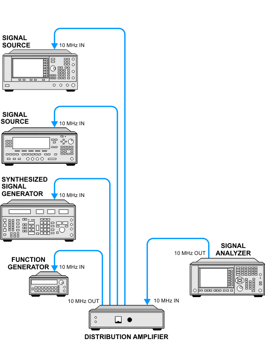
10 MHz Frequency Reference Connections
The 10 MHz connections shown in the test diagrams are displayed as a
direct connection between the EMI receiver and the signal source. If
the test equipment is used as a dedicated test system with multiple signal
sources, it might be more practical to employ a 10 MHz Distribution Amplifier.
The 10 MHz Distribution Amplifier (the 087A for example) allows a
single 10 MHz Reference to be connected to multiple 10 MHz inputs. The
Distribution Amplifier output power should be adjusted for a nominal +7
dBm with an input power of +3 dBm.
The following diagram shows how the Distribution Amplifier would be
connected to the test system.
|
|
Distribution
amplifiers tend to add large AC power related spurs onto the 10 MHz reference
signal. This can cause false failures in the Phase Noise < 30 kHz test
at the 100 Hz offset. If a failure is encountered in the Phase Noise <
30 kHz test, then remove the distribution amplifier from the signal path.
|
ESD Precautions
Protection against ESD (electrostatic discharge) is essential
while connecting, inspecting, or cleaning connectors attached to a static-sensitive
circuit (such as those found in test sets). Static electricity can build
up in your body and can easily damage sensitive internal circuit elements
when discharged. Static discharges too small to be felt can cause permanent
damage. Devices such as calibration components and units under test (UUTs)
can also carry an electrostatic charge. To prevent damage to the test
set, components and devices:
-
Always
wear a grounded wrist strap having a 1 million Ohm resistor in series
with it when handling components and devices or when making connections
to the test set.
-
Always
use a grounded antistatic mat in front of your test equipment.
-
Always wear
a heel strap when working in an area with a conductive floor. If you are
uncertain about the conductivity of your floor, wear a heel strap.