![]()
-
All test equipment requires a 30 minute warmup period to ensure accurate performance.
-
In the following test setup, cables are designated as solid lines and direct connections are designated as dashed lines.
This adjustment generates an FM flatness correction for the YIG Oscillator (YO) when the YO Phase Lock Loop (PLL) is open. Two correction values are generated and stored in a Programmable Gate Array (PGA) on the YO Driver. One correction value is generated at an FM deviation of 250 kHz with a rate of 500 kHz. The second value is generated at an FM deviation of 1000 kHz with a rate of 2000 kHz.
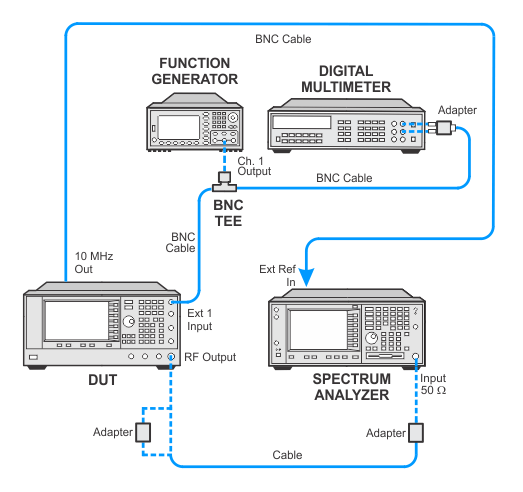
During this adjustment, a function generator is used to provide the baseband FM modulation. A digital multimeter ensures that the function generator amplitude is accurate. The signal generator is set up for 0 dBm at a carrier of 1 GHz. The EXT 1 input with AC-coupling is used by the signal generator. With FM turned on, a spectrum analyzer measures the modulation sidebands. A reference measurement for the flatness is first made at a deviation of 50 kHz with a rate of 100 kHz. The spectrum analyzer is tuned to the carrier frequency with a span capable of displaying the sidebands. The spectrum analyzer performs a marker-delta measurement between the amplitude of the carrier and the upper and lower sidebands. An average is calculated between the dBc values of the two measured sidebands.
The test equipment is then set for the test deviation and rate. The spectrum analyzer measurement is repeated. The calibration switches in different RC networks to change the shape of a low pass filter on the YO Driver. This is repeated until the differences between the amplitude of the test sidebands and the reference sidebands are at a minimum. If the differences in sidebands are greater than 1 dB, the adjustment fails.
|
Test Equipment |
Preferred Model |
Alternate Model(s) |
|
Digital Voltmeter |
3458A Opt 002 |
|
|
Spectrum Analyzer |
E444xA1 |
|
|
Function Generator |
33250A |
33120A Opt 001 |
1.Select any model of PSA spectrum analyzer (E4440A, E4443A,E4445A, E4446A, E4447A, E4448A) that has a maximum frequency greater than or equal to the maximum frequency of the unit under test. An E4448A is required for units with Option 567. The E4448A frequency range is adequate for all PSG-D frequency configurations.
|
|
|
Connect all test equipment as shown.
Connect GPIB cables to all GPIB-controlled test equipment.
While performing this adjustment, follow all instructions on the controller display.
Setup for FM/PM YO Frequency Compensation Calibration
If this adjustment fails, perform the following steps in order:
Check the equipment setup (see above). If the setup is incorrect, make the necessary corrections and rerun the adjustment.
Verify that the 10 MHz OUT of the spectrum analyzer is connected to the 10 MHz IN of the signal generator.
If this adjustment fails with the equipment setup properly, refer to the troubleshooting section of the signal generator's service guide. If you do not have a printed copy of the service guide (Option OBW), one is available either on the CD-ROM that came with your signal generator shipment or on the Keysight Website.
If you cannot correct the problem using the troubleshooting procedures in the Service Guide, obtain service from Keysight Technologies. Refer to Contacting Keysight Technologies.
