FM Path Offset Calibration
(E8257D, E8267D, E8663D with Option UNT and E8257N Only)
This adjustment generates a DAC value to null the voltage offsets on
the A6 Frac-N and A11 Pulse/Analog Modulation Generator.
During this adjustment, when FM is enabled the A6 Frac-N and A11 Pulse/Analog
Modulation Generator may generate unwanted voltage offsets. These voltage
offsets detune the Frac-N VCO from the desired frequency.
There are two FM Offset DACs, which generate a correction value for the external
inputs: internal FM and FM internally
grounded. The two external inputs can either be AC- or DC-coupled. With
all these different combinations, a total of 13 correction values are
generated and stored in FlashROM.
The adjustment algorithm uses a frequency counter to determine the Frac-N
nominal frequency. The frequency counter is used to calculate the FM Offset
DAC sensitivity (DAC counts/Hz). The correction DAC value is then calculated
and stored in FlashROM.
|
Test Equipment
|
Preferred Model
|
Alternate Model(s)
|
|
Frequency Counter
|
53230A Opt 010 and (106 or 115)
|
53132A Opt 010 and (050 or 124)
|
Connections and Setup Procedures
|

|
-
With the exception of the
53132A Option 050
or 124, or the 53230A Option 106 or 115 frequency counter, all test equipment
requires a 30 minute warmup period to ensure accurate performance.
-
The frequency counter must
be plugged into the AC power line for at least 24 hours before testing
begins.
-
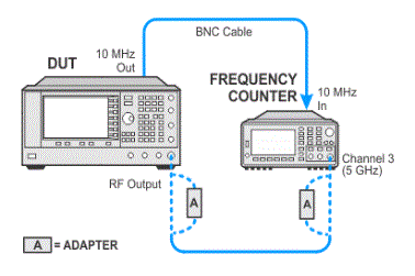
In the following test setup,
cables are designated as solid lines and direct connections are designated
as dashed lines.
|
-
Connect
all test equipment as shown.
-
Connect
GPIB cables to all GPIB-controlled test equipment.
-
While
performing this adjustment, follow all instructions on the
controller display.
Setup
for FM Path Offset Calibration

In Case of Difficulty
If this adjustment fails, perform the following steps in order:
-
Check the equipment setup (see above). If the setup
is incorrect, make the necessary corrections and rerun the adjustment.
-
If this adjustment fails with the equipment set up properly,
refer to the troubleshooting section of the signal generator's service
guide.
If you do not have a printed copy of the service guide (Option OBW),
one is available either on the CD-ROM that came with your signal generator
shipment or on the Keysight Website.
-
If you cannot correct the problem using the troubleshooting
procedures in the Service Guide,
obtain service from Keysight Technologies. Refer to Contacting Keysight Technologies.


![]()

