![]()
-
All test equipment requires a 30 minute warmup period to ensure accurate performance.
-
In the following test setup, cables are designated as solid lines and direct connections are designated as dashed lines.
This adjustment calibrates the upconverter gain at A37 45GHz.
The signal generator produces a single sideband p/4 DQPSK signal by having the I/Q data being all zeroes. The I/Q MUX attenuator is increased until the output signal is out of compression. The I/Q Gain Adjust DAC is varied until the proper gain of the A37 45 GHz Upconverter is achieved. This calibration is done for frequencies > 20 GHz.
|
Test Equipment |
Preferred Model |
Alternate Model(s) |
|
Power Meter |
N1914B |
N1914A1 |
|
Power Sensor |
N8487A |
8487A Opt H842 |
|
External Baseband Signal Generator |
E4438C Opt 402 and (001, 002, 601, or 602) | E8267D Opt (601 or 602) |
Option H84 provides reflection coefficient data.
|
|
|
Connect all test equipment as shown.
Connect GPIB cables to all GPIB-controlled test equipment.
While performing this adjustment, follow all instructions on the controller display.
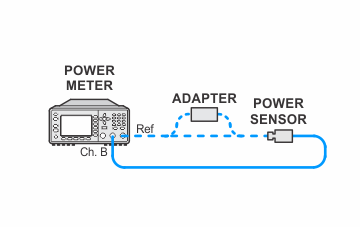
Setup for Power Meter Calibration
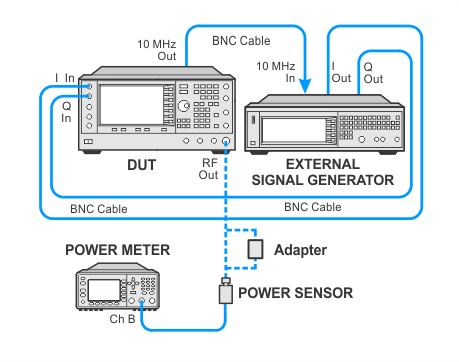
Setup for Upconverter Gain Calibration with Option 601 or 602
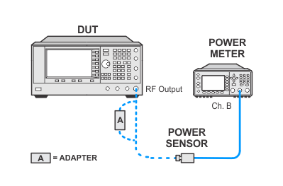
Setup for Upconverter Gain Calibration without Option 601 or 602
If this adjustment fails, perform the following steps in order:
Check the equipment setup (see above). If the setup is incorrect, make the necessary corrections and rerun the adjustment.
If this adjustment fails with the equipment set up properly, refer to the troubleshooting section of the signal generator's service guide. If you do not have a printed copy of the service guide (Option OBW), one is available either on the CD-ROM that came with your signal generator shipment or on the Keysight Website.
If you cannot correct the problem using the troubleshooting procedures in the Service Guide, obtain service from Keysight Technologies. Refer to Contacting Keysight Technologies.
