![]()
-
All test equipment requires a 30 minute warmup period to ensure accurate performance.
-
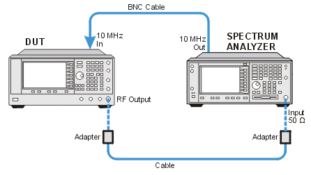
In the following test setup, cables are designated as solid lines and direct connections are designated as dashed lines.
This adjustment calibrates the A6 Frac-N for a stable VCO output at all frequencies and temperatures.
During this adjustment, the VCO frequency of A6 Frac-N is set to approximately
750 MHz. EE_Pot is adjusted until an oscillation (side bands) appears
at 15 MHz offset from the carrier. A baseline measurement of the side
bands is made using a spectrum analyzer. EE_Pot output is increased, which
increases the level of the side bands, until a significant side band is
present to ensure the side band level is distinguishable from the noise
floor. EE_Pot output is decreased until the baseline is reached. The voltage
on F_2_ABUS is measured.
The VCO output needs to be reduced by approximately 2 dB to ensure stability.
A high and low voltage limit is calculated using the F_2_ABUS voltage
that will result in a 2 dB drop in VCO output power. The calculated voltages
are used as the high and low voltage limits of a target range. EE_Pot
is adjusted until the voltage on F_2_ABUS falls within the calculated
range.
|
Test Equipment |
Preferred Model |
Alternate Model(s) |
|
Spectrum Analyzer |
E444xA1 |
|
1.Select any model of PSA spectrum analyzer (E4440A, E4443A,E4445A, E4446A, E4447A, E4448A) that has a maximum frequency greater than or equal to the maximum frequency of the unit under test. An E4448A is required for units with Option 567. The E4448A frequency range is adequate for all PSG-D frequency configurations.
2. Not allowed for the E8257N.
|
|
|
Connect all test equipment as shown.
Connect GPIB cables to all GPIB-controlled test equipment.
While performing this adjustment, follow all instructions on the controller display.
Setup for VCO Bias Frac-N Calibration

If this adjustment fails, perform the following steps in order:
Check the equipment setup (see above). If the setup is incorrect, make the necessary corrections and rerun the adjustment.
If a 856xE series spectrum analyzer is being used and the adjustment locks up, please check and ensure that the 856xE's external reference is connected. The spectrum analyzer will lock up and not take a sweep when external reference is selected and there isn't one connected to it.
If this adjustment fails with the equipment setup properly, refer to the troubleshooting section of the signal generator's service guide. If you do not have a printed copy of the service guide (Option OBW), one is available either on the CD-ROM that came with your signal generator shipment or on the Keysight Website.
If you cannot correct the problem using the troubleshooting procedures in the Service Guide, obtain service from Keysight Technologies. Refer to Contacting Keysight Technologies.
