![]()
-
All test equipment requires a 30 minute warmup period to ensure accurate performance.
-
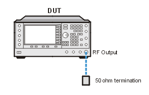
In the following test setup, cables are designated as solid lines and direct connections are designated as dashed lines.
This adjustment uses an internal firmware routine to perform this calibration. After the internal routine is complete the temporary calibration files from that routine are copied over to permanent storage. The internal firmware routine performs the tasks in the description below.
The purpose of this calibration is to determine the required I/Q gain, offset and quadrature calibration constant and array values that will minimize the I/Q modulation imperfections on the signals that the instrument provides. This program uses internal voltage sources and internal voltage detectors (on the I/Q Mux board and on the internal baseband generator board), measured by the internal ABUS, to perform the calibration. No external equipment is required (other than the controlling computer).
The calibrations performed by this program can be broken down into the following major sections:
Major Calibration Algorithm Sections
First, the program determines the I/Q Mux Board RMS-DC Converter Offset Imbalance compensation calibration constants.
Second, the program determines the I/Q Mux Board Main Path and External Output Path Attenuator non-linearity compensation calibration constants.
Third, the program determines the frequency-dependent I/Q Offset Imbalance compensation and Quadrature Imbalance compensation calibration constants associated with the I/Q modulator(s) and switchable filter paths on the Output Board(s).
Fourth, the program determines all of the I/Q Offset Imbalance compensation calibration constants associated with each of various paths through the I/Q Mux board. If the instrument has a baseband generator (BBG) installed, the I/Q Offset terms associated with it are also determined.
Fifth, the program determines the I/Q Gain Imbalance compensation calibration constants for the I/Q Mux Board. If the instrument has a BBG installed, the I/Q Gain Balance terms associated with it are also determined.
Sixth, the program determines the frequency-dependent I/Q Gain Imbalance compensation calibration constants associated with the I/Q modulator(s) and switchable filter paths on the Output Board(s).
|
Test Equipment |
Recommended Model |
|
50 Ohm Terminator1 |
Depending on the DUT RF Output Connector, choose: 85138B (2.4mm)
|
1. A 20 dB attenuator may be used as an alternative to a 50 Ohm Terminator.
|
|
|
Connect all test equipment as shown.
Connect GPIB cables to all GPIB-controlled test equipment.
While performing this adjustment, follow all instructions on the controller display.

If this adjustment fails, perform the following steps in order:
Check the equipment setup (see above). If the setup is incorrect, make the necessary corrections and rerun the adjustment.
If an "IQ Calibration Failed" error dialog occurs at the beginning of the adjustment, manually run the IQ calibration using the front panel and observe the errors on the DUT. If successful, repeat the test.
If this adjustment fails with the equipment set up properly, refer to the troubleshooting section of the signal generator's service guide. If you do not have a printed copy of the service guide (Option OBW), one is available either on the CD-ROM that came with your signal generator shipment or on the Keysight Website.
If you cannot correct the problem using the troubleshooting procedures in the Service Guide, obtain service from Keysight Technologies. Refer to Contacting Keysight Technologies.
