![]()
-
All test equipment requires a 30 minute warmup period to ensure accurate performance.
-
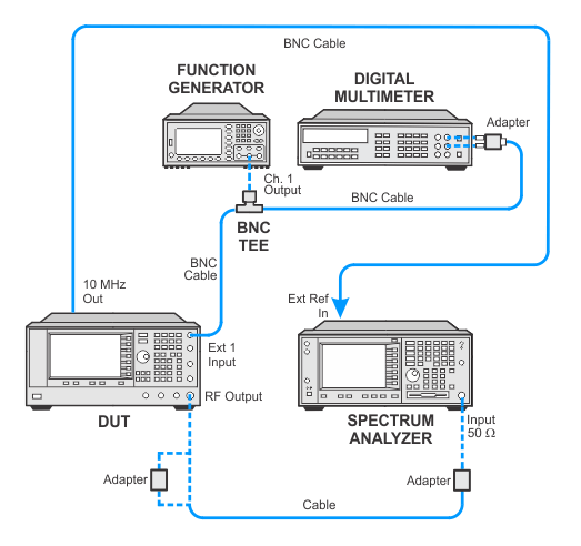
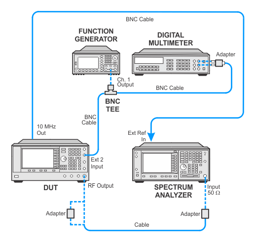
In the following test setup, cables are designated as solid lines and direct connections are designated as dashed lines.
Amplitude Modulation Rates tests the variation of the actual AM modulation depth at a given CW frequency for an external supplied modulation signal.
AM coupling and AM depth are set to applicable test point conditions, and the AM rate is set to a reference frequency of 1 kHz. The actual depth is measured with a spectrum analyzer in zero span and stored as the reference depth. With the coupling and depth settings held constant, the actual depth is measured for the corresponding AM rates. If the measured deviation is greater than the specified maximum deviation, the test fails.
|
Test Equipment |
Recommended Models |
Alternative Models |
|
Spectrum Analyzer |
N9030B Opt 5xx1 |
N9030A Opt 5xx1 E444xA2 |
|
Function Generator |
33622A |
33611A |
|
Digital Voltmeter |
3458A Opt 002 |
34470A |
|
|
|
|
Connect all test equipment as shown.
Connect GPIB cables to all GPIB-controlled test equipment.
While performing this performance test, follow all instructions on the controller display.
Amplitude Modulation Rates Test Setup (E8257N - External 1 Input)

Amplitude Modulation Rates Test Setup (E8257N - External 2 Input)

If this performance test fails, perform the following steps in order:
Check the equipment setup (see above). If the setup is incorrect, make the necessary corrections and rerun the Performance Test.
If this test fails with the equipment set up properly, refer to the troubleshooting section of the signal generator's service guide. If you do not have a printed copy of the service guide (Option OBW), one is available either on the CD-ROM that came with your signal generator shipment or on the Keysight Website.
If you cannot correct the problem using the troubleshooting procedures in the Service Guide, obtain service from Keysight Technologies. Refer to Contacting Keysight Technologies.
