DC FM Carrier Offset is a measure of carrier-frequency shift due to residual DC on the PSG’s EXT1 DC-coupled path when FM mode is selected. Any DC level in this path will cause a constant offset (deviation) in the CW frequency.
For this test, the PSG is set to a selected carrier frequency and FM is enabled. The EXT 1 input is selected and left open. A specific value of FM deviation is selected and a DC FM calibration is executed.
For FM on and FM off, the carrier frequency is measured with a frequency counter. Any shift in the carrier frequency must be due to a residual DC voltage somewhere in the EXT 1 input path.
DC-FM Carrier Offset definition:
![]()
|
Test Equipment |
Recommended Models |
Alternate Model(s) |
|
Frequency Counter |
53230A Opt 106 or 115 |
53132A Opt 050 or 124 |
|
|
|
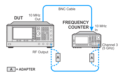
Connect all test equipment as shown.
Connect GPIB cables to all GPIB-controlled test equipment.
While performing this test, follow all instructions on the controller display.
Setup for DC FM Carrier Offset

If this performance test fails, perform the following steps in order:
Check the equipment setup (see above). If the setup is incorrect, make the necessary corrections and rerun the Performance Test.
If this test fails with the equipment set up properly, refer to the troubleshooting section of the signal generator's service guide. If you do not have a printed copy of the service guide (Option OBW), one is available either on the CD-ROM that came with your signal generator shipment or on the Keysight Website.
If you cannot correct the problem using the troubleshooting procedures in the Service Guide, obtain service from Keysight Technologies. Refer to Contacting Keysight Technologies.
