Timebase Utility

(Manual Utility only for options UNR, UNX, HNY, or UNY and units with Reference Board #E8251-60348)

This utility is not part of the E82x7D standard adjustment procedure and should not be performed as part of a calibration. Adjusting the frequency does not constitute an instrument failure and should not be reported as a failure.

  1. Remove the E82x7D external cover (refer to the Assembly Replacement in the E82x7D Service Guide for instructions) and set the DUT bottom side down for easy access to the 10 MHz Reference.

    The DUT and frequency counter need to warm up for 24 hours before performing this utility. If the DUT has been turned off for < 1 hour while the covers were removed, then wait 45 minutes after turning the instrument back on before adjusting the 10 MHz.

  2. Ensure the rear panel BNC short is connected to the EFC connector.

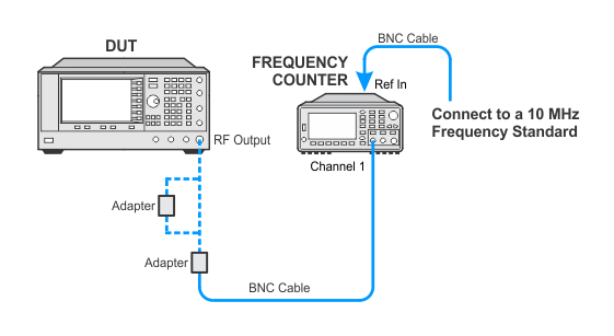
  3. Connect a house standard to a frequency counter and connect the E82x7D RF output to Channel 3 of a frequency counter.

  4. Set the DUT frequency to 1 GHz, power to 0 dBm, RF ON, and no external reference.

  5. To make the adjustment, insert the insulated screwdriver (access is in the top of the 10 MHz reference). Turning the screwdriver counter clockwise increases the frequency and clockwise decreases the frequency, remove the tuning tool before checking the frequency counter. Do not force the adjustment control to the limits; doing so will damage the control.

  6. Adjust the varactor for 1 GHz ±40 Hz (frequency counter reads <1000.000040 MHz and >999.999960 MHz). You may adjust the frequency closer if desired but the frequency may change when the covers are reinstalled or the instrument is moved.

  7. Once the adjustment is complete, let the instrument continue to operate for 1 hour and recheck the frequency. The frequency should be within 1 GHz ±100 Hz (<1000.000100 MHz and >999.999900 MHz).
Required Test Equipment

Test Equipment

Recommended Model

Alternate Model(s)

Frequency Counter

53230A Opt [106 or 115]

53132A Opt [050 or 124]


Connections and Setup Procedures

  • With the exception of the 53132A Option 050 or 124, or the 53230A Option 106 or 115 frequency counter, all test equipment requires a 30 minute warm-up period to ensure accurate performance.

  • The frequency counter must be plugged into the AC power line for at least 24 hours before testing begins.

  • In the following test setup, cables are designated as solid lines and direct connections are designated as dashed lines.

Connect all test equipment as shown.

In Case of Difficulty

If this adjustment fails, perform the following steps in order:

  1. Check the equipment setup (see above). If the setup is incorrect, make the necessary corrections and rerun the adjustment.

  2. If this adjustment fails with the equipment set up properly, refer to the troubleshooting section of the signal generator's service guide. If you do not have a printed copy of the service guide (Option OBW), one is available either on the CD-ROM that came with your signal generator shipment or on the Keysight Website.

  3. If you cannot correct the problem using the troubleshooting procedures in the Service Guide, obtain service from Keysight Technologies. Refer to Contacting Keysight Technologies.