- All test equipment requires a 30 minute warmup period to ensure accurate performance.
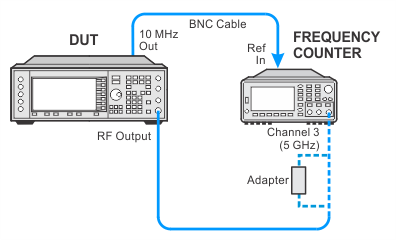
- In the following adjustment setup, cables are designated as solid lines and direct connections are designated as dashed lines.
The purpose of the DCFM adjustment is to remove all DC offsets associated with the FM path while in DC FM mode. This adjustment only uses the FM1 path to verify the functionality of the circuitry. The adjustment generates a correction voltage that is used to null any voltage offsets that are created by the Synthesizer or Reference Boards when FM is enabled. Without this adjustment, small voltage offsets may be generated that tune the Synthesizer VCO from the desired frequency.
During this adjustment, the instrument is set for a 1 GHz carrier at 0 dBm. Internal FM is turned on with the EXT1 FM input left open. The FM Deviation is set for 5.625 MHz for a standard ESG and 1 MHz for option UNJ. The FM1 path is selected with DC coupling. The instrument performs an internal calibration, which generates a frequency-offset value. This value is loaded into a register in an Application Specific Integrated Circuit (ASIC) on the Synthesizer Board.
A frequency counter is used to verify the corrected frequency is within +/– 3% of the theoretical value.
|
Test Equipment |
Recommended Model |
Alternate Model |
|
Frequency Counter |
53230A Opt [106 or 115] |
53132A Opt 010 and [050 or 124] |
|
|
|

If this adjustment fails, perform the following steps in order:
Check the equipment setup (see above). If the setup is incorrect, make the necessary corrections and rerun the adjustment.
If this adjustment fails with the equipment set up properly, refer to the troubleshooting section of the signal generator's service guide. If you do not have a printed copy of the service guide (Option OBW), one is available either on the CD-ROM that came with your signal generator shipment or on the Keysight Website.
If you cannot correct the problem using the troubleshooting procedures in the Service Guide, obtain service from Keysight Technologies. Refer to Contacting Keysight Technologies.
