
- All test equipment requires a 30 minute warmup period to ensure accurate performance.
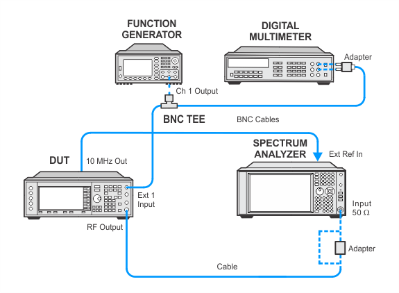
- In the following adjustment setup, cables are designated as solid lines and direct connections are designated as dashed lines.
This adjustment is only performed on units having Option UNJ. The adjustment generates an FM flatness correction for the YIG Oscillator (YO) for FM rates greater than 100 kHz. Two correction values are generated and stored in a Programmable Gate Array (PGA) on the YTF Driver board. One correction value is generated at an FM deviation of 100 kHz with a rate of 500 kHz. The second value is generated at an FM deviation of 2000 kHz with a rate of 1000 kHz.
During this adjustment, a function generator is used to provide the baseband FM modulation. A digital multimeter ensures that the function generator amplitude is accurate. The signal generator is set up for 0 dBm at a carrier of 1 GHz. The EXT1 input with AC coupling is used by the signal generator. With FM turned on, a spectrum analyzer measures the modulation sidebands. A reference measurement for the flatness is first made at a deviation of 20 kHz with a rate of 100 kHz. The spectrum analyzer performs a marker-delta measurement between the amplitude of the carrier and the upper and lower sidebands. An average is calculated between the dBc values of the two measured sidebands.
The test equipment is then set for the test deviation and rate. The spectrum analyzer measurement is repeated. The calibration switches in different RC networks to change the shape of a low pass filter on the YIG Driver. This is repeated until the differences between the amplitude of the test sidebands and the reference sidebands are at a minimum. If the differences in sidebands are greater than 1 dB, the adjustment fails.
|
Test Equipment |
Recommended Model |
Alternate Model |
|
Spectrum Analyzer |
N9030B Opt 5xx1 |
N9030A Opt 5xx1 E444xA2 Opt 233 |
|
Function Generator |
33622A |
33611A 33250A |
|
Digital Multimeter3 |
3458A Opt 002 |
None |
|
|
|
|
If this adjustment fails, perform the following steps in order:
Check the equipment setup (see above). If the setup is incorrect, make the necessary corrections and rerun the adjustment.
If this adjustment fails with the equipment set up properly, refer to the troubleshooting section of the signal generator's service guide. If you do not have a printed copy of the service guide (Option OBW), one is available either on the CD-ROM that came with your signal generator shipment or on the Keysight Website.
If you cannot correct the problem using the troubleshooting procedures in the Service Guide, obtain service from Keysight Technologies. Refer to Contacting Keysight Technologies.
