This adjustment requires firmware revision C.03.10 or later.
|
|
This adjustment requires firmware revision C.03.10 or later. |
The purpose of this calibration is to determine the I/Q timing skew adjustments required to minimize the I/Q timing skew of internally generated signals on the RF output. This adjustment will be required for a number of the unique I/Q baseband paths that exist from the baseband generator, through the instrument to the I/Q Modulator and ultimately to the RF output. The calibration is accomplished by applying identical multitone baseband signals to the I channel, the Q channel and then the I and Q channels simultaneously. The amplitudes are related in such a manner as to make it possible to calculate the quadrature error for each tone. The linear slope of the quadrature error versus modulation rate in radians/Hz is the timing skew error in seconds for the specific baseband setup condition.
|
Test Equipment |
Recommended Models |
Alternate Models |
|
Spectrum Analyzer |
N9030B Opt 5xx1 |
N9030A Opt 5xx1 |
|
|
|
|

If this adjustment fails, perform the following steps in order:
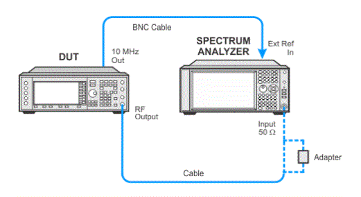
Check the equipment setup (see above). If the setup is incorrect, make the necessary corrections and rerun the adjustment.
If this adjustment fails with the equipment set up properly, refer to the troubleshooting section of the signal generator's service guide. If you do not have a printed copy of the service guide (Option OBW), one is available either on the CD-ROM that came with your signal generator shipment or on the Keysight Website.
If you cannot correct the problem using the troubleshooting procedures in the Service Guide, obtain service from Keysight Technologies. Refer to Contacting Keysight Technologies.
