
- All test equipment requires a 30 minute warmup period to ensure accurate performance.
- In the following adjustment setup, cables are designated as solid lines and direct connections are designated as dashed lines.
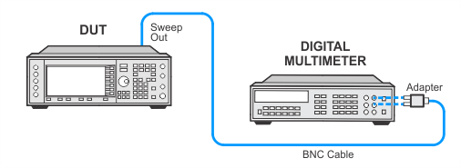
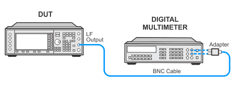
This adjustment is used to calibrate the Internal Source amplitude versus frequency. This adjustment will first default the offset and gain internal source calibration arrays. The offset cal factor is determined by measuring the difference between the DC offset motherboard common ground ABUS node and the DSP ABUS node. This is accomplished by connecting the DVM to the rear panel Sweep Out and setting the DSP to 0 Vdc. The scaling factors are determined by setting the DSP to output a full-scale sine wave with the DVM connected to the front-panel LF OUTPUT port. Measurements are made in 1-kHz steps and the cal factors are calculated to achieve 2 Vpeak on the motherboard.
|
Test Equipment |
Recommended Model |
Alternate Model |
|
Digital Multimeter |
3458A Opt 002 |
34470A |
|
|
|
Setup 1
Setup 2
If this adjustment fails, perform the following steps in order:
Check the equipment setup (see above). If the setup is incorrect, make the necessary corrections and rerun the adjustment.
If this adjustment fails with the equipment set up properly, refer to the troubleshooting section of the signal generator's service guide. If you do not have a printed copy of the service guide (Option OBW), one is available either on the CD-ROM that came with your signal generator shipment or on the Keysight Website.
If you cannot correct the problem using the troubleshooting procedures in the Service Guide, obtain service from Keysight Technologies. Refer to Contacting Keysight Technologies.
