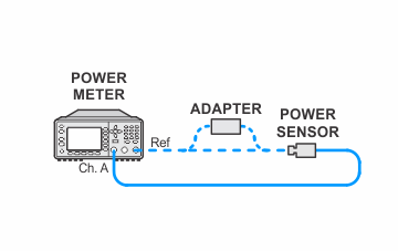
- All test equipment requires a 30 minute warmup period to ensure accurate performance.
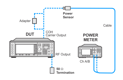
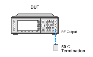
- In the following adjustment setup, cables are designated as solid lines and direct connections are designated as dashed lines.
Use this calibration to optimally set the prelevel reference DAC on the output board for use in the digital mode of operation.
The prelevel reference DAC on the output board is used to control the RF power level that is incident upon the I/Q modulator. It does this by setting the control point for the prelevel loop. The loop has a detector on an output of the I/Q modulator, its drive circuitry is also on the output board, but its RF modulator that it controls is on the Frac-N/synthesizer board. The goal of this calibration is to have sufficient power available at the I/Q modulator to perform the desired modulation (and have enough UUT output power available), while minimizing intermodulation distortion when digital modulation is in use.
For frequencies up to 4 GHz, a power meter measures the signal level at the input of the Output module (at the rear panel coherent carrier connector). For frequencies above 4 GHz, the ABUS is used to monitor the signal level on the high band output module.
|
Test Equipment |
Recommended Model |
Alternate Model |
|
Power Meter |
N1914B |
N1914A1 E4418A |
|
Power Sensor |
N8482A |
E9304A E9304A H18 N8482A CFT 8482A2 |
|
50 ohm Termination |
909A Opt 012 |
|
|
|
|
|
Power Meter Zero and Cal Setup for E4438C


Connection for E4428C

If this adjustment fails, perform the following steps in order:
Check the equipment setup (see above). If the setup is incorrect, make the necessary corrections and rerun the adjustment.
If this adjustment fails with the equipment set up properly, refer to the troubleshooting section of the signal generator's service guide. If you do not have a printed copy of the service guide (Option OBW), one is available either on the CD-ROM that came with your signal generator shipment or on the Keysight Website.
If you cannot correct the problem using the troubleshooting procedures in the Service Guide, obtain service from Keysight Technologies. Refer to Contacting Keysight Technologies.
