
- All test equipment requires a 30 minute warmup period to ensure accurate performance.
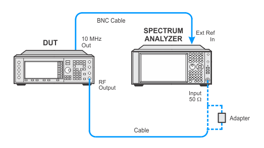
- In the following adjustment setup, cables are designated as solid lines and direct connections are designated as dashed lines.
The purpose of this adjustment is to set the VCO Bias Pot at a level that will keep the VCO in a stable operating region over all frequencies and temperatures. For ESGs without Option UNJ, the instrument is set to 750 MHz, and the pot is incremented 100 times to put the F/2 bias voltage at a minimum. Then the pot is decremented one count at a time with the spectrum analyzer tuned to 375 MHz looking for the F/2 spur to pop up. Once the spur pops up, a F/2 bias ABUS node measurement is made, and the pot is then incremented until the bias voltage is lowered by a half a volt.
For ESGs with Option UNJ, the F/2 signal is not easily accessible, so the adjustment is made in a different manner. The instrument is set to a frequency that places the Frac-N as close to 750 MHz as possible in ’r;B’ mode (this is about 780 MHz). Then the instrument is placed in the Sampler ’r;B’ mode of operation to minimize the amount of division that occurs before the signal reaches the RF output. The electronic pot is set to its highest setting and decreased until oscillation starts to occur. At this point a baseline measurement is made on the signal phase noise, skirt offset from the carrier by 15 KHz. The pot is then decremented until the phase noise skirt rises significantly and incremented until the phase noise skirt returns to its baseline level. The voltage at the SYNTH_F2 ABUS node is measured and then the pot is adjusted for an additional 0.77 to 0.8 V drop.
|
Test Equipment |
Recommended Models |
Alternate Models |
|
Spectrum Analyzer |
N9030B Opt 5xx1 |
N9030A Opt 5xx1 |
|
|
|
|
If this adjustment fails, perform the following steps in order:
Check the equipment setup (see above). If the setup is incorrect, make the necessary corrections and rerun the adjustment.
If this adjustment fails with the equipment set up properly, refer to the troubleshooting section of the signal generator's service guide. If you do not have a printed copy of the service guide (Option OBW), one is available either on the CD-ROM that came with your signal generator shipment or on the Keysight Website.
If you cannot correct the problem using the troubleshooting procedures in the Service Guide, obtain service from Keysight Technologies. Refer to Contacting Keysight Technologies.
