
This test is performed only on ESGs that have Option 001, 002, 601, or 602.
|
|
This test is performed only on ESGs that have Option 001, 002, 601, or 602. |
Error Vector Magnitude (EVM) is the magnitude of the vectorial difference between the measured signal and an ideal reference signal in the I-Q plane.
Global Phase Error is the magnitude of the phase difference between the measured signal and an ideal reference signal in the I-Q plane.
Shift Error is the magnitude of the frequency difference between the measured signal and an ideal reference signal in the I-Q plane. This is expressed as a % error from the desired frequency shift.
Deviation Accuracy is the magnitude of the frequency difference between the measured signal and an ideal reference signal in the I-Q plane. This is expressed as frequency difference from the desired frequency shift, in Hz.
Rho is the figure of merit for waveform quality. Waveform quality is the basic measure of the performance of a CDMA transmitter. Rho, also called the power correlation coefficient, is the percentage of transmitter power that correlates to the ideal code. Rho indicates how well the signal's power distribution matches the ideal power distribution. A value of 1.00 indicates that all of the transmitted power correlates with the ideal transmission code.
The ESG is programmed to produce many different digital modulation formats. The ESG must have Option 402 to generate TDMA signals, and Option 401 for CDMA signals.
This test supports two different test setups using either a PXA-series signal analyzer or an 89441A VSA spectrum analyzer. The PXA is the preferred solution.
The preferred solution uses a PXA-series signal analyzer with the 89600 Vector Signal Analysis Application to measure EVM.
|
Test Equipment |
Critical Specifications for This Test |
Recommended Models |
Alternate Models |
|
Spectrum Analyzer |
EVM Accuracy |
N9030B Opt 5xx1 and MPB2 |
N9030A3 Opt 5xx1 and MPB2 |
|
Vector Signal Analysis Application4 |
|
89600 VSA with these options5:
|
None |
|
The alternate solution uses an 89441A vector spectrum analyzer (VSA) to measure EVM and Global Phase Error. When using the VSA, additional equipment is required for downconverting the signal above 2.65 GHz.
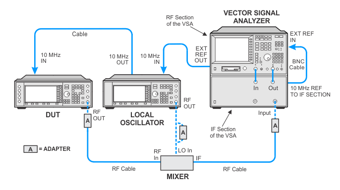
For test frequencies above 2.65 GHz (the upper limit of the 89441A vector signal analyzer), the digitally modulated RF signal is down-converted with an external mixer. The resultant IF signal is routed to the VSA’s input.
|
Test Equipment |
Critical Specifications for This Test |
Recommended Models |
Alternate Models |
|
Vector Signal Analyzer |
EVM Accuracy ≥ 1% |
89441A Opt AYA, AYH, AY9, B7A, and UFG or UTH
|
|
|
20 GHz Mixer |
Frequency Range: |
0955-2225
|
0955-1017 |
|
Local Oscillator |
Output Power: ≥ +16 dBM Frequency: 2 - 6 GHz |
E8267D Opt UNR or UNX or UNY
|
E4428C Opt 503 or 506 E8241A Opt UNJ E8247C Opt UNR E8257D Opt UNR or UNX or UNY N5181B/82B Opt [503 or 506] and Opt [UNX or UNY] N5182A Opt 1EA |
|
|
|
|
|
|
Install the 89600 Vector Signal Analysis Application on the same PC as TME.
Ensure that the PC where TME is installed is connected to the LAN.
Connect the PXA to the LAN.
Get the Hostname or IP address of the PXA via the PXA's front panel information system (System > Show > System).
Open the Keysight Connection Expert for the Keysight IO libraries and add the PXA to a LAN interface.
If a LAN interface does not exist, add it.
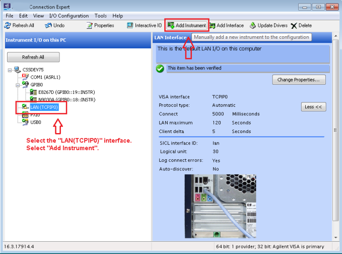

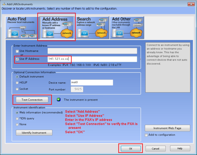
Add the PXA as an instrument on this interface using the Hostname or IP address from step 3a.
|
|
Using the PXA's Hostname is the preferred method to avoid the possibility of crashing the software. The Hostname can be found in the PXA's System menu. An example of a Hostname is: K-N9030B-80323, where K = Keysight, N9030B = model, 80323 = last 5 digits of the serial number. |
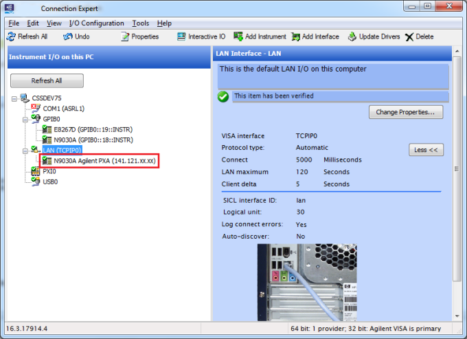
Verify that the instrument has been successfully added to the interface.
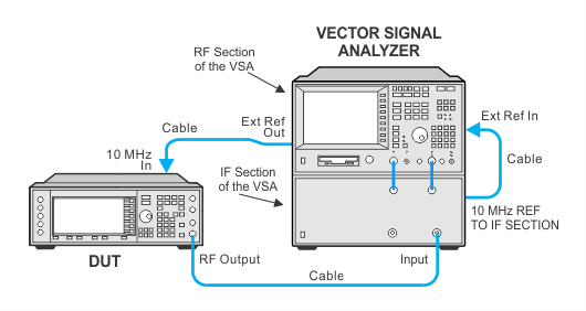
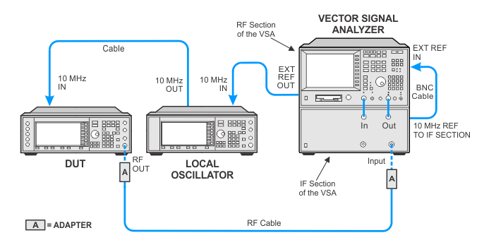
Ensure the equipment is connected as shown below:
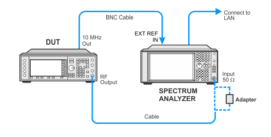
Test Setup for ESGs with < 3 GHz maximum frequency
Test setup without mixer for ESGs with ≥ 3 GHz maximum frequency
Test setup with mixer for ESGs with ≥ 3 GHz maximum frequency
When adding the PXA as LAN device, use the PXA's Hostname rather than the IP Address to avoid the possibility of crashing the software. The Hostname can be found in the PXA's System menu. An example of a Hostname is: K-N9030B-80323, where K = Keysight, N9030B = model, 80323 = last 5 digits of the serial number.
If the VSA software freezes during the Digital Modulation Quality test, manually verify that the you are able to “Rediscover Instruments” in the VSA software.
Open the VSA software and select Utilities >Hardware > Configurations…
Next, click on the Discover Instruments tab and click on the Rediscover Instruments button.
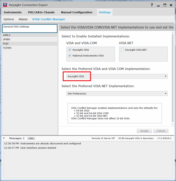
If this freezes, then you may need to set the Keysight VISA as the Preferred VISA. To set the Keysight VISA as the preferred VISA:
Open the Keysight Connection Expert and go to Settings > Visa Conflict Manager > General VISA Settings.
Ensure Keysight VISA is set as the preferred VISA implementation as shown in the image below:
 in the toolbar (webhelp only).