Power Level Accuracy
Power level accuracy is the difference between the power level indicated by the unit under test (UUT) and the true power delivered by the UUT.
Direct absolute power measurements are made with a power meter for higher power levels. A spectrum analyzer is used for all lower power measurements.
Required Test Equipment
|
Test Equipment
|
Recommended Models
|
Alternate Models
|
|
Power Meter
|
N1914B
|
N1914A1
N1913A
N1913B
E4418A
E4418B
E4419A
E4419B
|
|
Power Sensor
|
N8482A
|
E9304A
E9304A H18
E9304A H19
N8482A CFT
8482A2
U8481A Option 200
U8485A Option 200
|
|
Spectrum Analyzer
|
N9030B Opt 5xx4, MPB, Pxx5
|
N9030A Opt 5xx4, MPB, Pxx5
N9030A/B Opt 5xx4, MPB
N9030A/B Opt 5xx4, Pxx5
N9030A/B Opt 5xx4
E444xA3
Opt 110 and 123
E444xA3 Opt 1DS, 123
E444xA3 Opt 1DS
E444xA3 Opt 110
E444xA3 Opt 123
E444xA3
|
Connections and Setup Procedures
|

|
-
All test equipment requires a 30 minute warm-up period to ensure accurate
performance.
-
In the following test setup, cables are designated as solid lines and direct
connections are designated as dashed lines.
-
At low power levels, residual spurs from adjacent instruments can cause the UUT
to fail the test. Therefore, the instruments must be adequately separated from
one another. Do not place one device on top of another. If the test fails at
very low power levels, offset all frequencies by +25 Hz or -25 Hz and manually verify. This will shift the test frequency away from
possible residual responses.
|
-
Connect
all test equipment as shown.
-
Connect
GPIB cables to all GPIB-controlled test equipment.
-
While
performing this test, follow all instructions on the controller display.
Flexible power sensor channel assignment
This test uses flexible power sensor channel assignment and will identify the channel that a power sensor is connected to using the ability of "smart" sensors such as the N848xA, U848xA, and E930xA series to report their full model and serial number. Legacy 848x series power sensors are unable to provide their model or serial number, but their channel is identified during the sensor calibration process by identifying the channel of the sensor connected to the calibrator.
If the wrong legacy power sensor is connected to the calibrator during this process the error can be resolved by disconnecting and reconnecting the power sensor to the power meter which will force a new calibration.
Select from the links below for connection setups depending on the power sensor.
 Setup using standard power sensors
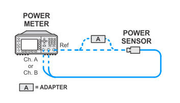
Power sensor calibration — standard sensors
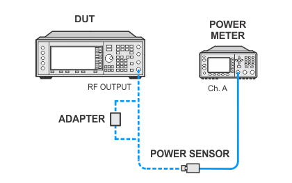
Power meter measurements (high powers) — standard sensors channel A
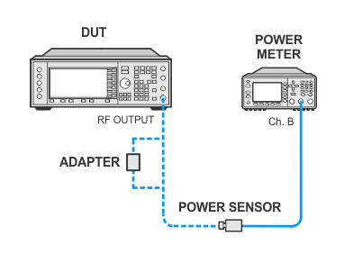
Power meter measurements (high powers) — standard sensors channel B
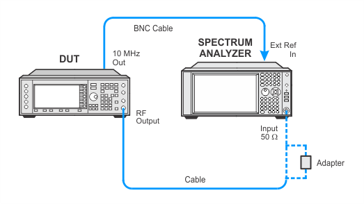
Low Powers

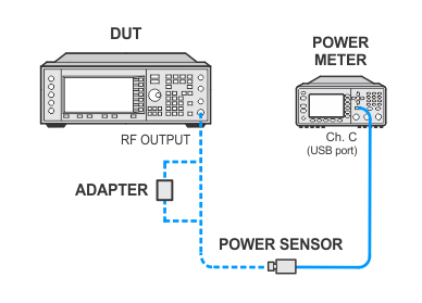
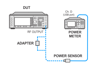
 Setup using USB power sensors
Power sensor calibration — USB sensors
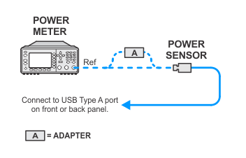
Power meter measurements (high powers) — USB sensors channel C
Power meter measurements (high powers) — USB sensors channel D
Low Powers


In Case of Difficulty
-
Sometimes noise from nearby test equipment can affect low-level
measurements. Errors may be caused even if the power meter is stacked on top of
the spectrum analyzer.
-
Inspect all RF cables. If semi-rigid cables are used, check for
cracks in the shielding or at the connectors. RF leakage to/from the cables
generally cause problems at higher frequencies (> 2 GHz) and low power levels (< -100 dBm).
-
Verify that the spectrum analyzer does not have a residual spur at
the frequency being measured. Sometimes a spur will limit how low in power the
spectrum analyzer can measure.
-
Make sure that all test equipment is using the same power outlet.
Ground loops can cause problems at low power levels. This type of problem will
most likely show up at lower frequencies.
-
Make sure all covers on the DUT are secure and that all screws are in
place.
-
Verify the amplifier being used meets its gain specifications.
-
Make sure all connections in the measurement system are torqued
properly. Loose or damaged connections result in RF leakage and errors result at
low power levels.
-
Make sure all test equipment (including the amplifier) has been
turned on at least 45 minutes.

![]()


