
- All test equipment requires a 30 minute warmup period to ensure accurate performance.
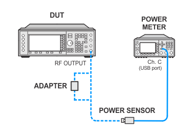
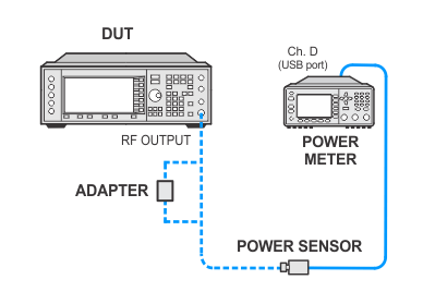
- In the following test setup, cables are designated as solid lines and direct connections are designated as dashed lines.
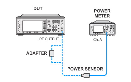
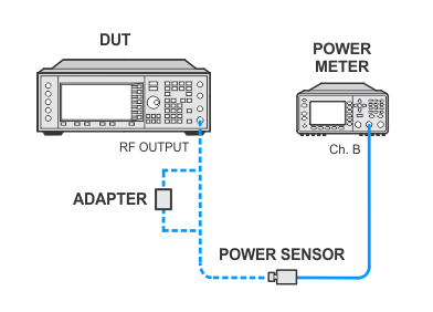
This test verifies that the maximum output power from the UUT meets specifications. During this test, the signal generator is set to its maximum settable output power and a measurement is performed using a power meter.
|
Test Equipment |
Critical Specifications for This Test |
Recommended Models |
Alternate Models |
|
Power Meter |
None |
N1914B |
N1914A1 E4418A |
|
Power Sensor |
None |
N8482A |
E9304A E9304A H18 E9304A H19 N8482A CFT 8482A2 U8481A Option 200 U8485A Option 200 |
Power meter N1914A with serial numbers ranging between MY00000000—MY53040007 require Service Note 07 to be applied for measurement repeatability. Please have this service note applied or verify it was applied before using this power meter. The affected service note is N1914A-07.
Not allowed for the following product configurations:
The dynamic frequency range of this sensor is insufficient for these models.
|
|
|
This test uses flexible power sensor channel assignment and will identify the channel that a power sensor is connected to using the ability of "smart" sensors such as the N848xA, U848xA, and E930xA series to report their full model and serial number. Legacy 848x series power sensors are unable to provide their model or serial number, but their channel is identified during the sensor calibration process by identifying the channel of the sensor connected to the calibrator.
If the wrong legacy power sensor is connected to the calibrator during this process the error can be resolved by disconnecting and reconnecting the power sensor to the power meter which will force a new calibration.
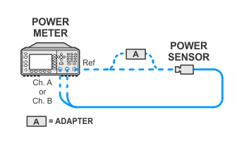
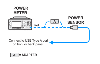
Select from the links below for connection setups depending on the power sensor.

If this performance test fails, perform the following steps in order:
Check the equipment setup (see above). If the setup is incorrect, make the necessary corrections and rerun the performance test.
If this test fails with the equipment set up properly, refer to the troubleshooting section of the signal generator's service guide. If you do not have a printed copy of the service guide (Option OBW), one is available either on the CD-ROM that came with your signal generator shipment or on the Keysight Website.
If you cannot correct the problem using the troubleshooting procedures in the Service Guide, obtain service from Keysight Technologies. Refer to Contacting Keysight Technologies.