Digital Modulation Quality
N5162A / N5182A Option 651, 652, or 654
N5172B Option 653 or 655 or 657
N5182B / N5182N Option 656 or 657
Error
Vector Magnitude (EVM) is the
magnitude of the vectorial difference between the measured signal and
an ideal reference signal in the I-Q plane.
Global Phase
Error is the magnitude of the phase difference between the measured
signal and an ideal reference signal in the I-Q plane.
This test supports two different test setups using either a PXA (N9030A/B) signal analyzer with Vector Signal Analysis Application, or an 89441 vector spectrum analyzer. The PXA is the preferred solution.
-
A PXA-series (N9030A/B) signal analyzer is used with the 89600 Vector Signal Analysis Application to measure EVM and Global Phase Error.
A PSA-series spectrum analyzer (E4443A, E4440A, or E4445A) with Option 241 (Flexible Digital Modulation Personality) and B7J (Digital Demodulation Hardware) and Option 123 (Preselector Bypass)4 may also be used to measure EVM and Global Phase Error.
|
Test Equipment
|
Critical Specifications for This Test
|
Recommended Model
|
Alternate Models
|
|
Signal Analyzer
|
EVM Accuracy
|
N9030B Opt 5xx1 and MPB2
|
N9030A Opt 5xx1 and MPB2
E4440A3 Opt 241, B7J, and 1234
E4443A3 Opt 241, B7J, and 1234
E4445A3 Opt 241, B7J, and 1234
|
|
Vector Signal Analysis Application5
|
|
896006, 7 VSA with these options:
|
|
|
-
An 89441A vector spectrum analyzer is used to measure EVM and Global Phase Error. When using the 89441A, additional equipment is required for downconverting the signal above 2.65 GHz.
|
Test Equipment
|
Critical Specifications for This Test
|
Recommended Model
|
Alternate Models
|
|
Vector Signal Analyzer
|
EVM Accuracy
|
89441A Opt AYA, AYH,
AY9, B7A, and UFG or UTH
|
|
|
Mixer
|
Frequency Range:
RF: L.O. Ports:
200 MHz – 20 GHz
I.F. Port: 5 MHz – 6 GHz
|
0955-2225
|
0955-1017
|
|
Local Oscillator
|
Output power1:
≥ 16 dBm
Frequency: 2 – 6 GHz
|
E8257D Opt [UNR or UNX or UNY]
|
E8241A Opt UNJ
E8244A Opt UNJ
E8251A Opt UNJ
E8254A Opt UNJ
E8247C Opt UNR
E8257C Opt UNR
E8267C Opt UNR
E8267D Opt [UNR or UNX or UNY]
|
|
10 dB Attenuator
|
None
|
8491B Opt 010
|
8490D Opt 010
8491B Opt 010
8493A Opt 010
8493B Opt 010
8493C Opt 010
|
|
Connections and Setup Procedures
|

|
|
For setup instructions using either the PXA or PSA signal analyzer,
 click here
.
Test Setup Instructions for PXA with the Vector Signal Analysis Application
|
|
- The PXA's firewall may need to be turned off.
- The PXA must be logged in as Administrator.
|
-
Install the 89600 Vector Signal Analysis Application on the same PC as TME. This PC must also be connected to the LAN.
-
Connect the PXA signal analyzer to the LAN.
-
Get the IP address of the PXA via the PXA’s front panel information system: System > Show > System.
-
Add the PXA to the LAN interface.
-
Open the Agilent Connection Expert for the Agilent IO libraries. If a LAN interface does not exist, add it:
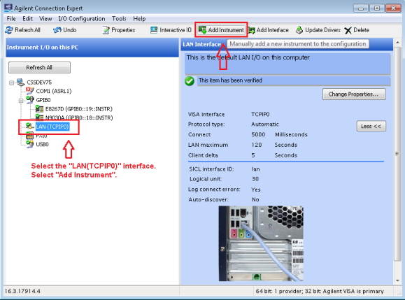
-
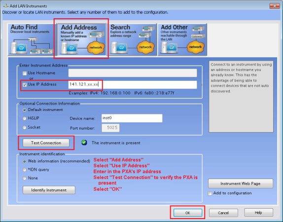
Add the PXA as an instrument on this interface using the IP address from step 3.
-
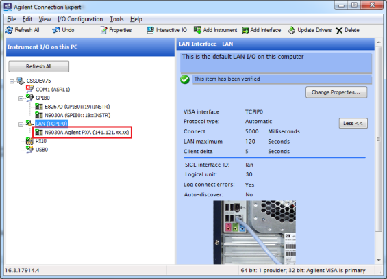
Verify that the instrument has been successfully added to the interface.
|
|
See below for troubleshooting tips if using VSA software 89601B version 21.0 or greater with Keysight IO libraries.
|
-
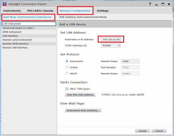
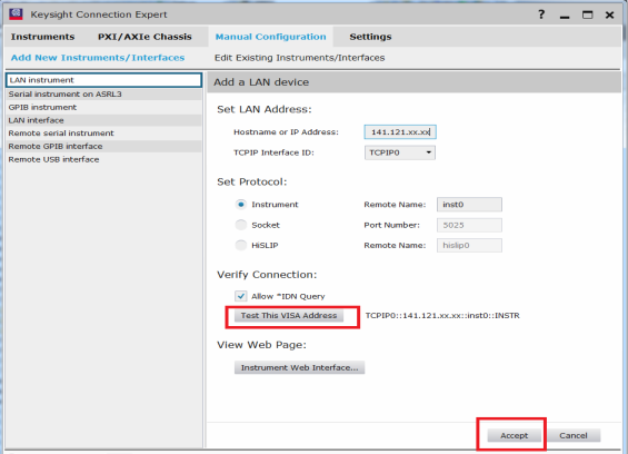
Open the Keysight Connection Expert for the Keysight IO libraries and add the PXA to a LAN interface by selecting Manual Configuration > Add New Instrument/Interfaces > LAN instrument.
-
Add the PXA as a LAN device by entering the PXA's Hostname (preferred method) or IP address as shown below.
|
|
Using the PXA's Hostname is the preferred method to avoid the possibility of crashing the software. The Hostname can be found in the PXA's System menu. An example of a Hostname is: K-N9030B-80323, where K = Keysight, N9030B = model, 80323 = last 5 digits of the serial number.
|
-
Verify the instrument address by selecting Test This VISA Address, then select Accept.
-
Ensure the equipment is connected as shown (PXA or PSA):
For setup instructions using the 89441 VSA,
click here:
Vector Spectrum Analyzer Test Setup
Setup for all RF frequencies
Setup for RF frequency ≤ 2650 MHz
Setup for RF frequency > 2650
MHz
Vector Signal Analysis Troubleshooting
When adding the PXA as LAN device, use the PXA's Hostname rather than the IP Address to avoid the possibility of crashing the software. The Hostname can be found in the PXA's System menu. An example of a Hostname is: K-N9030B-80323, where K = Keysight, N9030B = model, 80323 = last 5 digits of the serial number.
Troubleshooting tips if using VSA software 89601B version 21.0 or greater with Keysight IO libraries:
If the VSA software freezes during the Digital Modulation Quality test, manually verify that the you are able to “Rediscover Instruments” in the VSA software.
- Open the VSA software and select Utilities >Hardware > Configurations…
-
Next, click on the Discover Instruments tab and click on the Rediscover Instruments button.
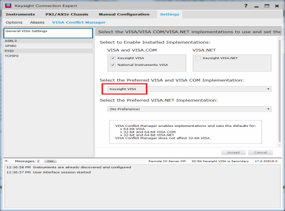
If this freezes, then you may need to set the Keysight VISA as the Preferred VISA. To set the Keysight VISA as the preferred VISA:
-
Open the Keysight Connection Expert and go to Settings > Visa Conflict Manager > General VISA Settings. Ensure Keysight VISA is set as the preferred VISA implementation as shown in the image below:

 in the toolbar (webhelp only).