![]()
All test equipment requires a 30 minute warmup period to ensure accurate
performance.
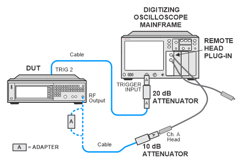
In the following test setup, cables are designated as solid lines and direct
connections are designated as dashed lines.
This test verifies that the pulse level accuracy of the internal pulse modulator meets specifications.
During the test, the peak-to-peak amplitudes of the CW and PULSE ON signals are measured with a high-frequency, digitizing oscilloscope. The signal generator is placed in CW mode at a certain power level and an oscilloscope is used to measure the peak-to-peak excursion. The signal generator is then pulse modulated by its internal pulse generator and the peak-to-peak measurement is repeated with an oscilloscope.
|
Test Equipment
|
Critical Specifications for This Test |
Recommended Model |
Alternate Model(s) |
|
High Frequency Oscilloscope Mainframe |
None |
N1000A |
86100A/B/C/D |
|
Oscilloscope Plug-In |
None |
N1045B1 |
N1045A1 86117A |
|
10 dB Attenuator |
None |
8493C Opt 010 |
8490D
Opt 010 |
|
20 dB Attenuator |
None |
8493C Opt 020 |
8490D
Opt 020 |
|
|
|
All test equipment requires a 30 minute warmup period to ensure accurate
performance. |
Connect all test equipment as shown.
Connect GPIB cables to all GPIB-controlled test equipment.
If using the N1045A/B or N1055A oscilloscope plugin, the N1000A or 86100D oscilloscope mainframe must be in the FlexDCA and not the Legacy UI configuration. If necessary, select Apps > FlexDCA from the user interface. (The 86100D can be in either the FlexDCA or Legacy UI configurations when used with dual-slot plug-ins such as the 54752A or 86112A plug-ins.) When switching configurations, be sure that the GPIB address is correctly set in the new configuration. The FlexDCA and Legacy UI configurations maintain independent GPIB addresses which is why TME is unable to automatically switch to the proper configuration.
While performing this performance test, follow all instructions on the controller display.

 click here:
If this performance test fails, perform the following steps in order:
Check the equipment setup (see above). If the setup is incorrect, make the necessary corrections and rerun the performance test.
Refer to the troubleshooting section of the service guide. If you do not have a printed copy of the service guide (Option OBW), one is available either on the CD-ROM that came with your signal generator shipment or search for your signal generator model number on the Keysight website.
If necessary, obtain service from Keysight Technologies. Refer to Contacting Keysight Technologies.
