Non-Harmonic Spurious

(N5161A / N5162A / N5166B / N5171B / N5172B / N5181A / N5181B / N5182A / N5182B / N5182BX07 / N5182N)

Non-harmonic spurious responses are unwanted signals that are not related to the fundamental output frequency of the DUT that are produced by the internal frequency synthesis of the DUT. This test utilizes a spectrum analyzer to measure the amplitude of these responses relative to the amplitude of a fundamental frequency.

The spectrum analyzer and the signal generator are both tuned to the harmonic frequency and a reference amplitude measurement is made. Then, the signal generator is tuned to the fundamental frequency with the power level unchanged. The spectrum analyzer measures the resulting harmonic response relative to the reference amplitude. For spurious signals close to the fundamental where phase noise dominates over thermal noise, an additional noise measurement is made to correctly determine the measurement uncertainty due to noise.

The N5182BX07 requires the Extender Power Alignment procedure to be performed prior to running Performance Verification test plans. Refer to the N5182BX07 User's Guide for instructions on running the Extender Power Alignment. To access the User's Guide, go to Keysight support.
Required Test Equipment

Test Equipment

Critical Specifications for This Test

Recommended Model

Alternate Model(s)

Spectrum Analyzer

None

N9030B Opt 5xx1

N9030A Opt 5xx1
E444xA2

Signal Generator

  • For N5182BX07 only

None

N5182B Opt. 506, 1EA, FRQ


  1. Select any option of PXA spectrum analyzer (503, 508, 513, 526, 543, 544, 550) that has a maximum frequency greater than or equal to the maximum frequency of the unit under test. The N9030A/B Option 550 frequency range is adequate for all DUT frequency configurations.
  2. Select any model of PSA spectrum analyzer (E4440A, E4443A, E4445A, E4446A, E4447A, E4448A) that has a maximum frequency greater than or equal to the maximum frequency of the unit under test. The E4448A frequency range is adequate for all DUT frequency configurations.

Connections and Setup Procedures

  • All test equipment requires a 30 minute warmup period to ensure accurate performance.
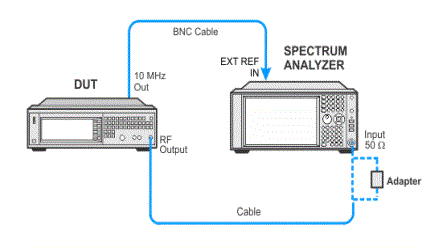
  • In the following test setup, cables are designated as solid lines and direct connections are designated as dashed lines.
  1. Connect all test equipment as shown.
  2. Connect GPIB cables to all GPIB-controlled test equipment.
  3. While performing this test, follow all instructions on the controller display.


Test Setup

Test Setup, N5182BX07

In Case of Difficulty

If this performance test fails, perform the following steps in order:

  1. Check the equipment setup (see above). If the setup is incorrect, make the necessary corrections and rerun the performance test.

  2. Refer to the troubleshooting section of the service guide. If you do not have a printed copy of the service guide (Option OBW), one is available either on the CD-ROM that came with your signal generator shipment or search for your signal generator model number on the Keysight website.

  3. If necessary, obtain service from Keysight Technologies. Refer to Contacting Keysight Technologies.