External Phase Modulation
Frequency Response
ΦM deviation frequency responseverifies
the phase-modulation deviation flatness while varying the modulation
rate. A reference value is taken at a 1 kHz rate.
A measurement receiver is used to measure the
FM deviation. The FM deviation is then divided by the modulation rate
to determine the ΦM
Deviation.
ΦM deviation frequency
response is checked for CW frequencies 550 MHz and 1.0 GHz. If
the DUT meets the specification in this frequency range, accuracy in all
other frequency ranges will be assured. Each frequency is tested with
the following sequence:
-
A reference signal is measured.
-
The set deviation measurement
is measured for each applied rate change.
-
Each deviation measurement is
compared to the reference signal deviation.
Required Test Equipment
|
Spectrum Analyzer
|
FM Deviation Accuracy
|
E444xA2 Opt 1DS, 1233
|
|
Function Generator
|
none
|
33250A
|
|
Digital Voltmeter
|
AC True-RMS Accuracy
|
3458A Opt 002
|
- Refer to the main equipment list for alternate models.
- Depending on your frequency range
needs, choose either an E4440A, E4443A, E4445A, E4446A, or E4448A. (E4447A is for Power Level Accuracy adjustment only.)
- Options 1DS and 123 are for ESGs > 3 GHz.
|
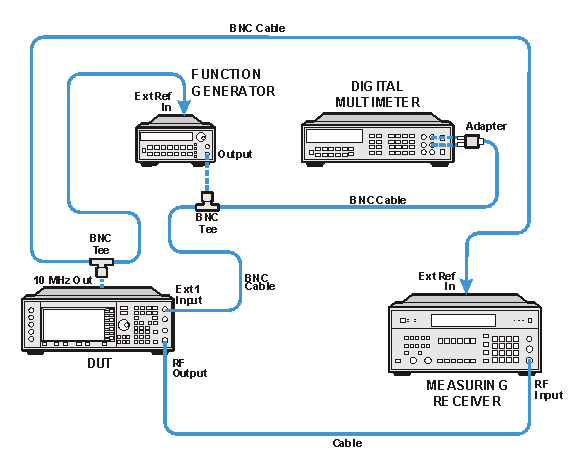
Connections and Setup Procedures
|

|
- All test equipment requires a 30 minute warm-up period to ensure accurate
performance.
- In the following test setup, direct cable and adapter connections are designated
as solid lines. Changeable cable and adapter connections are designated
as dashed lines.
- Connect all test equipment as shown.
- Connect
GPIB cables to all GPIB-controlled test equipment.
- While
performing this test, follow all instructions on the controller display.
|
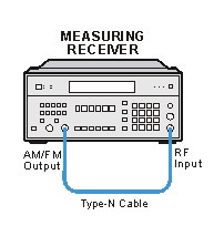
Measuring Receiver Calibration
Setup
Phase Modulation Frequency Response
Test Setup