![]()
This test is not a performance test. This check is only provided to insure that the dual arbitrary waveform generator is operational. There are no specifications for this check.
This check verifies the functionality of the dual arbitrary waveform generator. A triangular waveform is downloaded into the signal generator and then output to the rear-panel I and Q outputs. An oscilloscope is used to monitor the rear-panel I and Q outputs.
|
|
This test is not a performance test. This check is only provided to insure that the dual arbitrary waveform generator is operational. There are no specifications for this check. |
|
Instrument |
Recommended Model |
|---|---|
|
Oscilloscope |
High Frequency
Oscilloscope Mainframes: Oscilloscope Plug-Ins: Dual-Channel Oscilloscopes: |
|
10 dB Fixed Attenuator |
8491B Option 010 |
Connections and Setup Procedures
|
Note |
All test equipment requires a 30 minute warm-up period to ensure accurate
performance. |
Connect equipment as shown. The oscilloscope is not connected to GP-IB; this allows for the use of most general 2-channel oscilloscopes.
Set the oscilloscope to display both Channel 1 and Channel 2. Set the oscilloscope to trigger on Channel 1.
The recommended settings are:
Vertical Scale: 100 mV/div
Timebase: 100 mSeconds/div
Trigger: Freerun
Input Impedance: 50 Ohms
Verify that Channel 1 and Channel 2 are both displaying triangular waveforms approximately 180 degrees out of phase and that they do not have any discontinuities. Refer to the illustration below.
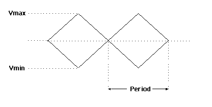
Frequency is approximately 2.7 Hz.
Amplitude is approximately:
Dual-Channel Oscilloscope
Vmax 300 mV
Vmin –300 mV
High Frequency Oscilloscope
Vmax 95 mV
Vmin –95 mV
Both waveforms are symmetrical around 0 volts (the average voltage is approximately 0V).
