Connection Setups
|
|
Due to the complexity of the PNA family of analyzers, the following notes apply to illustrations in the PNA Help:
|
N5244AS, N5245AS with Option H29
Jitter is a statement of the receiver stability of a noise signal, and defined here as the RMS deviation of the measurement of the signal. The noise measurement works by taking multiple noise power samples from the noise receiver and averages them to produce a single noise measurement.
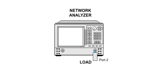
The system under test is set to measure a cold noise source over the whole system bandwidth. A cold noise source is defined as a source that produces noise power that is the result of purely thermal origin and proportional to room temperature. A standard impedance matched load will be used as the source. The load is passive so all the noise will be thermally created by temperature. Also, using a load will insure that there is no added reflection.
The noise receiver is set to the desired state including IF filtering, gain, and the number of samples to measure. A load is connected to the noise receiver. We assume that the load produces a flat cold noise-response through the whole frequency range.
The receiver system is set to the desired measurement state and when the system has stabilized, the noise measurement is taken. The standard deviation and mean of the sweep in its raw non-corrected state is determined and used to derive the jitter.
For troubleshooting help, see Noise Jitter Troubleshooting.
|
Test Equipment |
Recommended Model |
Alternate Model |
|
Termination 50 W 3.5 mm |
85052B |
85052D |
|
Termination 50 W 2.4 mm |
85056A |
none |
|
Termination 50 W 1.85 mm |
85058B |
none |
|
|
Due to the complexity of the PNA family of analyzers, the following notes apply to illustrations in the PNA Help:
|