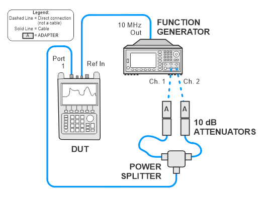
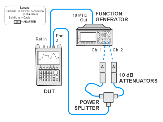
Port 1 is always tested. Port 2 is only tested if Option 211 is installed.
N9925A/26A/27A/28A
|
|
Port 1 is always tested. Port 2 is only tested if Option 211 is installed. |
There are two solutions for this test: a test-set only solution and a dual solution that can use either the test set or a function generator. The FieldFox firmware version will determine which solution can be used. TME will detect the firmware version of the FieldFox.
Test limits are related to the specifications for Corrected Measurement Uncertainty.
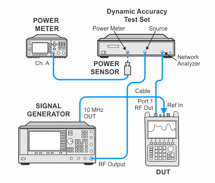
This solution can only use the Z5623A-H01 test set.
The Z5623A-H01 test set is used to measure dynamic accuracy of the A and B receivers down to -41 dBm. A reference power of -1 dBm is used for the test. Measurements are not made below -41 dBm because of noise interference at lower power levels.
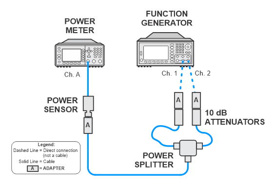
With this solution, either the test set or the function generator can be used. The test set is the preferred method. Depending on the test equipment mapped, TME will determine the solution. If both the test set and function generator are mapped, TME will use the test set as the preferred solution. If the test set is not mapped, then TME will use the function generator solution providing that the function generator is mapped. Note that only the 33622A function generator is allowed for this test; no other function generator models are allowed. If neither the test set nor the 33622A function generator are mapped, the user will be prompted to map one of the solutions.
|
|
The test process prompts for a 30 minute wait to allow the temperature of the power sensor to stabilize. This wait may not be required if the power sensor is already stable. |
|
Test type: |
functional |
|
Related specification: |
none (Dynamic Accuracy is a factor in Corrected Measurement Uncertainty.) |
|
Related adjustment: |
none |
|
Test Equipment |
Recommended Model1 |
|---|---|
|
Preferred solution with test set2 |
|
|
Signal Generator #1 |
E8257D with options:
|
|
Power Meter |
N1914A |
|
Power Sensor |
N8482A |
|
Dynamic Accuracy Test Set |
Z5623A Opt. H01 |
|
Alternate solution with function generator2 |
|
|
Function Generator |
33622A3 |
|
Power Meter |
N1914A |
|
Power Sensor |
N8482A |
|
Power Splitter |
11667B |
|
Attenuator, fixed, 10 dB
|
8493C Option 010 |
|
Cables and adapters |
|
|
Cable, Type-N (m) to Type-N (m) |
11500C |
|
Adapter, 3.5 mm (f) to Type-N (f) |
1250-1745 |
|
Adapter, 2.4 mm (f) to Type-N (f) |
11903B |
|
|
|
The following notes apply to illustrations in the FieldFox Help:
|
|
|
For the two cables between the power splitter and attenuators, choose short but flexible cables. For best results, the cable between the attenuator on channel 1 of the function generator and power splitter should be of longer length than the cable from the attenuator on channel 2 |