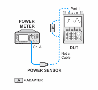
Port 2 is only tested if Option 122 is installed.
The following procedure is performed on each port that is to be tested. First, the maximum power output by the NA source at CW frequencies across the frequency range of the FieldFox. Then the linearity of the source step attenuator is tested at 1 GHz. The reference receiver is used to measure the linearity. For each attenuator setting, the measured value is normalized to the power output level produced when the attenuator is set to zero dB. The measured error is calculated by subtracting the nominal attenuator setting from the absolute value of the measured value. The limits on the measured error are based on a population of attenuators with typical characteristics.
|
|
Port 2 is only tested if Option 122 is installed. |
|
Test type: |
functional |
|
Related specification: |
Test Port Output Power (nominal) |
|
Related adjusment: |
none |
|
Test Equipment |
Recommended Model Number |
|---|---|
|
Power Meter |
N1914A |
|
Power Sensor |
E9304A Opt. H18 |
|
Power Sensor Cable |
11730A |
|
|
The following notes apply to illustrations in the FieldFox Help:
|

