IF Frequency Response Test

This test applies to the following models:

IF Frequency Response is the maximum amplitude deviations of a signal within the IF bandwidth relative to a reference signal at the center of the IF bandwidth.

In this test several center frequencies are used, each in the center of the band to test the IF Frequency response. For each band, the center frequency is changed to the middle of the band and then, with an 8 MHz span, the test initiates the routine in the firmware to sweep the signal. The result that is measured is the relative amplitude for each point in the trace data.

Test type:

functional

Related specification:

There is no specification or typical that directly drives this test. This test confirms that IF flatness is acceptable. It confirms that the IF Frequency Response adjustment was performed successfully.

Required Test Equipment

The network analyzer used in this test must be calibrated prior to running the test. The calibration will need to be repeated once every three days or if the connectors or cables have been disturbed. If it's been within the three day time frame and the connectors and cables have not been disturbed, then the network analyzer calibration is not necessary and you may proceed with the test.

For a list of required equipment and calibration instructions to perform the network analyzer calibration, go to the Network Analyzer Calibration Procedure topic page.

Test Equipment

Recommended Model Number

(see main equipment list for alternative models)
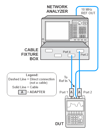
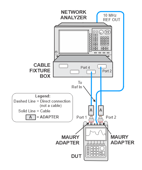
Network Analyzer

N5247B with options:

  • 425
  • 560: R-channel calibration option
  • S93080B: frequency offset

Cable, 1.85 mm (f) to 1.85 mm (m)

  • 2 required

JUNFLON J12J102905-00-2

Cable, BNC (m) to BNC (m)

8120-2582

Barrel adapter, 2.4 mm (f) to Type-N (m)

11903D

Barrel adapter, 2.4 mm (f) to Type-N (m)

11901B

Maury adapter, 3.5 mm (m) to Type-N (m)

  • 2 required
  • For N9938B Type-N (no Option 100)

Maury CC-A-35N-MMM


Connection Setups

The following notes apply to illustrations in the FieldFox Help:

  • Only a single representative model will be shown.
  • Some illustrations may differ than those in TME.
  • For procedures that apply to multiple ports, illustrations will show the setup on only one test port.

IF Frequency Response Test Setup

IF Frequency Response Test Setup
N9938B Type-N