Eq Impulse Response (Custom OFDM)
The trace for Custom OFDM Orthogonal Frequency Division Multiplexing: OFDM employs multiple overlapping radio frequency carriers, each operating at a carefully chosen frequency that is Orthogonal to the others, to produce a transmission scheme that supports higher bit rates due to parallel channel operation. OFDM is an alternative tranmission scheme to DSSS and FHSS. modulation is the equalizer impulse response for measurement hardware input channel X (where X is the number of the channel) and the specified spatial stream (MIMO Multiple Input, Multiple Output: A physical layer (PHY) configuration in which both transmitter and receiver use multiple antennas.).
Channel Equalizer Impulse Response shows the impulse response of the equalization filter. The Equalizer Training parameters determines what technique is used to calculate the ChX Eq Impulse Response trace.
| Equalizer Training | Description |
|---|---|
| Preamble Only | The Eq Impulse is computed using only the Channel Estimation Sequence (HT high throughput-LTF Long Training field) portion of the preamble. |
| Preamble & Data | The Eq Impulse is computed using both the Channel Estimation Sequence (HT-LTF) portion of the preamble and the data symbols. This option is typically the more accurate selection. |
The result length will be four times the FFT Fast Fourier Transform: A mathematical operation performed on a time-domain signal to yield the individual spectral components that constitute the signal. See Spectrum. length.
Ch Eq Impulse Response for Custom modulation is similar to the Digital Demodulation Eq Impulse Response. The differences are:
- Digital Demodulation typically uses a running average to average multiple scans when computing the equalizer impulse response. Custom OFDM modulation does not average, but computes a new equalizer response for each burst.
- The equalization
filter is inherent to Custom OFDM modulation, it is not optional, cannot be enabled/disabled,
like Digital Demod.
The 802.11n standard does not allow more spatial streams than channels. However, the standard does allow more channels than spatial streams, the VSA software does not support this configuration.
Understanding MIMO Trace Data Results
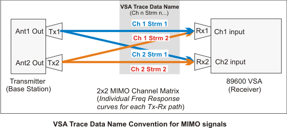
There is a channel Equalizer Impulse response trace data result for each input channel and spatial stream (Ch X Strm X) path for the measurement MIMO system.
For example, a 2x2 MIMO system is comprised of 2 input channels and 2 spatial streams and therefore has four channel Equalizer Impulse response trace data results, one for each input-channel/spatial-stream path; 1) Ch1 Strm1, 2) Ch1 Strm 2, 3) Ch2 Strm 1, and 4) Ch 2 Strm 2 (where "Ch" is the VSA measurement hardware input channel and "Strm" is the spatial stream). The following graphic shows the trace data naming convention for multi-channel 2x2 MIMO system.
The number of Equalizer Impulse response measurements expand as the MIMO size, number of spatial streams and number of channel inputs increase as shown in the following table:
| Number of Input Channels | Equalizer Impulse Response Measurements | ||
| 1 | Stream1 Ch1 | ||
| 2 | Stream1 Ch1 | Stream2 Ch1 | |
| Stream1 Ch2 | Stream2 Ch2 | ||
| 3 | Stream1 Ch1 | Stream2 Ch1 | Stream3 Ch1 |
| Stream1 Ch2 | Stream2 Ch2 | Stream3 Ch2 | |
| Stream1 Ch3 | Stream2 Ch3 | Stream3 Ch3 | |
In general, the VSA only supports MIMO configurations with 1 data stream per input channel. However, there are a few exceptions, see 802.11n/ac book, 802.11n/ac Measurement Capabilities topic for more information.
See Also