Phase Err (Digital Demod)
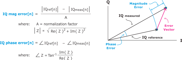
(Phase Error) is the phase difference between the I/Q reference signal and the I/Q measured signal, averaged over all symbol points.
The magnitude of this error data is an indicator of the quality of the phase component of the modulated signal. For example, a very high phase error might indicate high incidental FM Frequency Modulation modulation on the signal.
The phase error shown in the trace is computed only at the symbol times (the instant in time when symbols are detected). The computation does not include points between symbols. Therefore, the value of has no effect on this error data.
The also shows the symbol that has the largest phase error (the peak phase error).
OQPSK Offset Quadrature Phase Shift Keying: A type of QPSK modulation that offsets the bit streams on the I and Q channels by a half bit. This reduces amplitude fluctuations and helps improve spectral efficiency./SOQPSK uses two points-per-symbol (symbols and midpoints between symbols) to compute phase error and the peak phase error due to the offset between I and Q.
For the MSK Minimum Shift Keying demodulation format, the analyzer uses ALL points to compute phase error. Therefore, changing the value of affects phase error when MSK is selected.
For the EDGE Enhanced Data for Global Evolution: A technology that gives GSMA and TDMA similar capacity to handle services for the third generation of mobile telephony. EDGE was developed to enable the transmission of large amounts of data at a high speed, 384 kilobits per second. (It increases available time slots and data rates over existing wireless networks.) demodulation format, the EVM Error vector magnitude (EVM): A quality metric in digital communication systems. See the EVM metric in the Error Summary Table topic in each demodulator for more information on how EVM is calculated for that modulation format., Phase, and Magnitude Error data results may vary for different points/symbol settings. When points/symbol is set to 1 (default), the trace data results are compensated for ISI Inter-Symbol Interference: An interference effect where energy from prior symbols in a bit stream is present in later symbols. ISI is normally caused by filtering of the data streams. (inter-symbol interference). For points/symbol greater than one, the trace data results are not compensated for the effects of ISI.
See Also