IQ Gain Imbalance and Quadrature Skew Error Data Interaction (Digital Demod)
IQ Gain Imbalance and Quadrature Error are defined and evaluated relative to a chosen I/Q reference axis. Often the reference is obvious, such as for 64 QAM Quadrature Amplitude Modulation. For other formats such as 8 PSK Phase Shift Keying: A broad classification of modulation techniques where the information to be transmitted is contained in the phase of the carrier wave., the reference must be established manually or by synchronizing to known data patterns.
A factor in IQ Gain Imbalance and Quadrature Error evaluation is the symbol mapping of a modulator. For example the VSA chooses an "off-axis" mapping of the symbols for QPSK Quadrature phase shift keying, yielding points at (0.707, 0.707), (0.707, -0.707), (-0.707, -0.707), and (-0.707, 0.707). Some modulators may implement QPSK using an "on-axis" mapping of symbols, yielding points at (1.0, 0.0), (0.0, -1.0), (-1.0, 0.0), (0.0, 1.0). In this second case, the symbols¾though estimated correctly¾have a different IQ axis relative to the modulator symbol mapping upon demodulation in the VSA. This is apparent because the constellation diagram has symbol decision points in the "off-axis" locations instead of in the locations used in the modulator mapping as shown in figure 1. This 45° shift of reference affects only the IQ Gain Imbalance Error and Quadrature Error data of the Symbols/Errors table in the VSA.
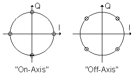
Figure 1: Two possible constellation mappings for QPSK.
When a signal contains Quadrature skew, the error could be reported as IQ Gain Imbalance if the signal generator has a mapping that is different from the VSA receiver. The reverse is also true. IQ Gain Imbalance is characterized by a gain difference between I and Q channels. This equates to a rectangular stretch along the ideal I/Q axes, once DC offset, phase and amplitude errors have been minimized, as shown in figure 2. Likewise, Quadrature Error is created when the I/Q axes are not exactly 90° apart, leading to a rectangular stretch along a 45° line, as shown in figure 4. When the constellation mapping is incorrect, a 45° rotation is added to the symbols. With a Quadrature Error, the rectangular off-axis stretch is rotated onto the ideal I/Q axes yielding IQ Gain Imbalance. Likewise, the same 45° rotation converts an on-axis rectangular stretch into an off-axis stretch interpreted as Quadrature Error. These results are shown graphically in the differences between figures 4 and 5.
The VSA Digital Demodulation software allows the constellation to be rotated, changing the skew and imbalance calculations. For the example above, a value of 45° will cause the error data to be calculated relative to the "on-axis" mappings. Note the symbol detection locations are rotated with the data but the bit state definitions are relative to the 0° case so bit data output will not change with rotation.
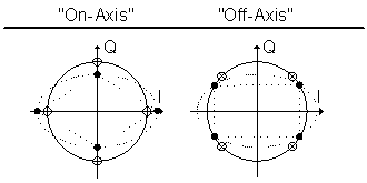
Figure 2: QPSK with IQ Gain Imbalance.
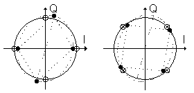
Figure 3: QPSK with Quadrature Error.
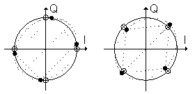
Figure 4: QPSK with Quadrature Error, corrected for DC offset, phase, and amplitude errors.
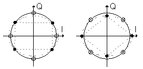
Figure 5: QPSK with Quadrature Error corrected for DC offset, phase, and amplitude errors, but with incorrect state mapping.
For coherent modulation formats, Constellation Sync Search should be used to create a consistent phase reference relative to the I/Q modulator mapping. If this cannot be accommodated, or the modulation format cannot provide such information (As for Pi/4 DQPSK Differential Quadrature Phase Shift Keying: QPSK modulation using differential encoding of the digital information stream. and EDGE Enhanced Data for Global Evolution: A technology that gives GSMA and TDMA similar capacity to handle services for the third generation of mobile telephony. EDGE was developed to enable the transmission of large amounts of data at a high speed, 384 kilobits per second. (It increases available time slots and data rates over existing wireless networks.)), it is recommended to use the rotation parameter with single sweep mode to analyze IQ Gain Imbalance and Quadrature Skew. Averaging does not provide reliable results for IQ Gain Imbalance and Quadrature Error in cases without a consistent phase reference1. This analysis can give information regarding the extent of the problem but if the problem includes both IQ Gain Imbalance and Quadrature Skew isolation of the two error data results is not possible without extended information.
Also note that slight variations in measurement results occur depending on points chosen to be included in the IQ Gain Imbalance and Quadrature Skew algorithms. By default, the VSA software calculates IQ Gain Imbalance and Quadrature Skew using the same point selection as the other measurements. This includes choosing only the symbol decision points for most formats, with the notable exceptions of OQPSK Offset Quadrature Phase Shift Keying: A type of QPSK modulation that offsets the bit streams on the I and Q channels by a half bit. This reduces amplitude fluctuations and helps improve spectral efficiency. and MSK Minimum Shift Keying. OQPSK requires an even number of points for accurate results and MSK results depend heavily upon trajectory points between the sample locations. The parameter in the tab of the dialog box, controls how the calculations are performed. Selecting this checkbox forces the calculations to be performed using the requested number of points per symbol. Leaving the checkbox cleared results in sending only symbol decision points to the calculation. The default values are typically correct but increased sensitivity to effects occurring between symbol decision points may be more apparent by choosing to couple the measurements to points per symbol.
Special considerations for EDGE demod format
With EDGE, the modulation scheme is 3Pi/8 8PSK. The 3Pi/8 rotation per symbol interval makes IQ Gain Imbalance and Quadrature Error measurements ambiguous, as the phase relative to the midamble may be arbitrary. If the particular modulator has known data characteristics for when the rotation is started (i.e. at the beginning of the frame or with a particular training sequence), these can be used with markers to determine the correct rotation to obtain the correctly decoupled IQ Gain Imbalance and Quadrature Error data results. In addition, the ISI Inter-Symbol Interference: An interference effect where energy from prior symbols in a bit stream is present in later symbols. ISI is normally caused by filtering of the data streams. compensation provided by the VSA software makes it advisable to take IQ Gain Imbalance and Quadrature Skew measurements with the measurement filter turned off and with points per symbol set to a value greater than one2. This is not a "clean" plot but it is still correct and is a result of the EDGE modulation format.
- This does not apply to Pi/4 DQPSK when Constellation Sync Search is enabled, as the phase ambiguity is ±90°. This known ambiguity leads exclusively to changes in sign for IQ Gain Imbalance and Quadrature Skew. This is taken into account in the VSA software by averaging only magnitude values of IQ Gain Imbalance and Quadrature Skew.
- One point-per-symbol is the preset default for EDGE. This provides a "clean" constellation plot and provides measurement ISI cancellation.
See Also