Sequential Input Configuration
is a dialog you can use to conveniently configure Massive MIMO Measurements using a switch matrix and Sequential Input Channel Acquisition. The parameters in this dialog are mainly about the signal transmitted by the device under test (DUT Device under Test: An acronym used to describe some type of electrical apparatus connected to test instrumentation. The apparatus can range from a single component to a complex subsystem such as a mobile phone, base station or MSC.) and the DUT ports connection. Based on some assumptions, the VSA software will use these parameters to configure the logical channel to measurement channel mapping, the sequential acquisition number, and the power/frequency of the measurement channels.
General
DUT Carrier Freq - The center frequency of the signal transmitted by DUT.
DUT Carrier BW - Frequency bandwidth of the signal transmitted by DUT.
Analyzer Input Range - The power range of the signal fed to the analyzer input port. Normally the DUT transmits the signal at some power, then there is some attenuator between the DUT output port and Analyzer input port, as VSA needs to know the power level fed to the Analyzer input port so that it can adjust the analyzer gain/attenuation properly to get the best performance.
Switch Attenuation - When a switch is connected in the test system, and if there is attenuator on the switch paths, customer can configure the attenuation for all paths here.
Channel Mapping
DUT Ch. Count - The number of DUT output ports to be measured (N).
Analyzer Ch. Count - The number of Analyzer input ports used for the measurement (M).
Sequential Phase/Time Tracking On - If Sequential Input Channel Acquisition is needed, do we use a reference channel to track the phase/time changes during the Sequential Input Channel Acquisition.
Tracking Channel Through Switch - If Sequential Phase/Time Tracking On is true, does the tracking channel go through the switch matrix or not?
Connection Scenarios
If N > M, a switch matrix is needed to connect the DUT and the Analyzer. Since the VSA doesn't provide specific parameters to configure the switch matrix (which input ports are used and which output ports are used), the VSA makes the following assumptions on the connections between DUT, Switch Matrix and Analyzer based on the four Channel Mapping parameters.
Connection Scenario 1: Sequential Phase/Time Tracking On = False
This configuration assumes that the first N input ports of the switch matrix are connected with the N DUT ports, and the first M output ports of the switch matrix are connected with the M Analyzer Input ports. The sequential acquisition number is Ceiling( N / M). The cable connection diagram between DUT/Switch/Analyzer is shown below.
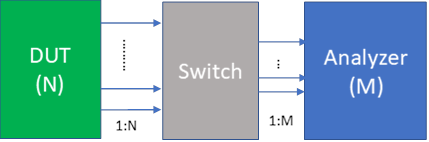
If no switch matrix is selected, or the input port count of the switch matrix is smaller than N, or the output port count of the switch matrix is smaller than M, an Invalid Configuration message will show up in the status area.
Connection Scenario 2: Sequential Phase/Time Tracking On = True, Tracking Channel Through Switch = False
This configuration assumes that the first output port of the DUT is connected to the first input port of the Analyzer.
Then the rest of N – 1 DUT ports are connected to the first N – 1 input ports of the switch matrix;
And the M – 1 output ports of the switch matrix are connected with the remaining M – 1 input ports of the Analyzer. The sequential acquisition number is Ceiling((N-1)/ (M-1)). The cable connection diagram between DUT/Switch/Analyzer is shown below.
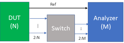
If no switch matrix is selected, or the input port count of the switch matrix is smaller than N - 1, or the output port count of the switch matrix is smaller than M - 1, or the Analyzer channel number M < 2, an Invalid Configuration message will show up in the status area.
Connection Scenario 3: Sequential Phase/Time Tracking On = True, Tracking Channel Through Switch = True
This configuration assumes that the first N input ports of the switch matrix are connected with the N DUT ports, and the first M output ports of the switch matrix are connected with the M Analyzer Input ports. The sequential acquisition number is Ceiling((N-1)/ (M-1)). The cable connection diagram between DUT/Switch/Analyzer is shown below.
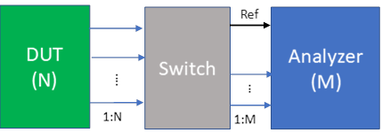
If no switch matrix is selected, or the input port count of the switch matrix is smaller than N, or the output port count of the switch matrix is smaller than M, or the Analyzer channel number M < 2, an Invalid Configuration message will show up in the status area.
If N = M, no switch matrix is needed. DUT N output ports are connected with the N analyzer input channels directly, and the sequential acquisition number is 1. The connection diagram is shown below:

If N < M, the analyzer has more channels than needed.
See Also