VITA 49, VITA 49A and VITA 49.2
Sharing Data With Other Applications
You can recall VITA 49 packets from a recording file in *.vita49, *.pcap or *.pcapng format, allowing you to share recordings between the VSA software and other programs that support VITA 49, VITA 49A and VITA 49.2 files. VITA 49 is a packet-based protocol to convey digitized signal data and metadata (or context data) pertaining to different reference points within a radio receiver.
To load and run an example VITA 49 recording, click and navigate to %PROGRAMFILES%\Keysight\89600 Software <ReleaseVersion>\89600 VSA Software\Help\Signals\Vita49. Choose the file type and select the CW_1M_40MBW_vita49_2.vita49 example, then click .
Supported Payload Format Types
Data format
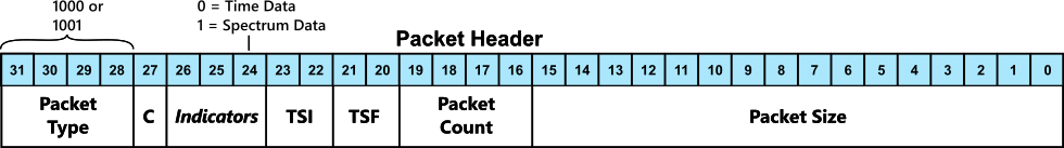
The VSA software supports the VITA 49.2 data format. In the Packet Header (shown below), bit 25 indicates the data format. This bit is set to "0" for data format 49.0 and "1" for data format 49.2.

Packet Type
The VSA software supports three types of packets: Signal Data Packet without Stream Identifier, Signal Data Packet with Stream Identifier, and Context Packet. The VSA software ignores the stream identifier in the packets, so all signal data packets in the file will be treated as if they don't have a stream identifier.
| Packet Type Bits (31-28) | Description | Supported by VSA | |
| 0000 | Signal Data Packet without Stream Identifier | YES | |
| 0001 | Signal Data Packet with Stream Identifier | YES (Stream Identifier ignored) | |
| 0010 | Extension Data Packet without Stream Identifier | NO | |
| 0011 | Extension Data Packet with Stream Identifier | NO | |
| 0100 | Context Packet | YES |
TSI (Integer Timestamp)
| TSI Bits (23-22) | Description | VSA Support | |
| 00 | No timestamp | Absolute time markers won't reflect absolute time from the VITA 49 packets | |
| 01 | UTC time (includes leap seconds) | Used for absolute time markers in VSA as well as segment start times when using segmented capture* | |
| 10 | GPS Global Positioning System:L A worldwide radio-navigation system that was developed by the US. Department of Defense. In addition to military purposes it is widely used in marine and terrestrial navigation (for example car navigation systems). time | Used for absolute time markers in VSA as well as segment start times when using segmented capture* | |
| 11 | Other (depends upon the OUI definition) | Used for absolute time markers in VSA as well as segment start times when using segmented capture. Only supported for the DIFI OUI which defines it as POSIX time but does not include leap seconds* |
*You can enable timestamps in VSA or convert to a different time standard in the Display Preferences > Marker > Timestamps dialog.
TSF (Fractional Timestamp)
| TSF Bits (23-22) | Description | VSA Support | |
| 00 | No fractional timestamp | Absolute time markers in VSA will not show the correct time | |
| 01 | Sample Count fractional timestamp | Absolute time markers in VSA support this | |
| 10 | Real Time (picoseconds) fractional timestamp | Absolute time markers in VSA support this | |
| 11 | Free Running Count Timestamp | Not supported |
Signal Data Packets
Signal Data Packets (Type 0000 or 0001) are indicated as either Time Data (0) or Spectrum Data (1) by bit 24 of the Data Header. The VSA software will recall data payload in Time Data packets only.
*If bit 26 is set to 1 then the trailer indicator bits will be used by the VSA software (see the State and Event Indicators table for how they are used). Note: If a trailer is present in the signal data packet then any indicator bits there that are enabled will be used instead of the equivalent ones in the context packet.
Supported Payload Format Types
For supported payload format types in VSA, please check the sections below:
VITA 49.0 (49/49A) and VITA 49.2 Payload Formats
For VITA 49, VITA 49A and VITA 49.2, payload types are defined in context packets.
Within the context packet (shown below), bit 15 needs to be set to 1.
If Signal Data Packet Payload Format exists (bit 15 = 1), we can get detailed info from the Data Packet Payload Format Field (in Context packet).

The VSA software has the following Data Packet Payload Format Field requirements:
-
Real/Complex (bits 30, 29) value needs to be 01 (Complex Cartisan)
-
The following combinations are supported for Data Item Format and Data Item Size:
VITA 49.0 (49/49A)
Data Item Format Data Item Size SignedFixedPoint
4-15*, 16
SinglePrecisionFloatingPoint
32
*Data Item Size of 4 through 15 are additionally supported when the Item Packing Field Size is the same as the Data Item Size and when the Packing Method is Link Efficient. The 16 bit Data Item Size does not have these dependencies.
VITA 49.2
Data Item Format Data Item Size Packing Field Size SignedFixedPoint
16
16
SignedFixedPoint
32
32
SinglePrecisionFloatingPoint
32
32
SignedFixedPointNonNormalized
16
16
ODI Payload Format
For ODI, payload type information is taken from the ClassId part in the Data packet. A file is treated as an ODI file if the OUI field ClassId in the Data packets is AXLe = 245CCB or Keysight = 800902 (see ODI ClassId definition below).

The VSA software processes ODI data packets whose fields in the ClassId satisfy the following requirements:
| ODI ClassId Field | Value | |
|
Pad Bit Count |
00000 |
|
|
Reserved |
000 |
|
|
OUI |
0x245CCB for AXIe-defined formats 0x800902 for Keysight-defined formats |
|
|
Pad Word Count |
0000 |
|
|
ODI Reserved |
00 |
|
|
Fixed Value |
00 |
|
|
Event |
00 = none |
|
|
R/C |
01 = Complex IQ |
|
|
Data Type |
0011 000= 16-bit Signed Fixed Point 0100 000= 32-bit Signed Fixed Point |
|
|
Vector Size |
0 0000 0000 0000 for one channel |
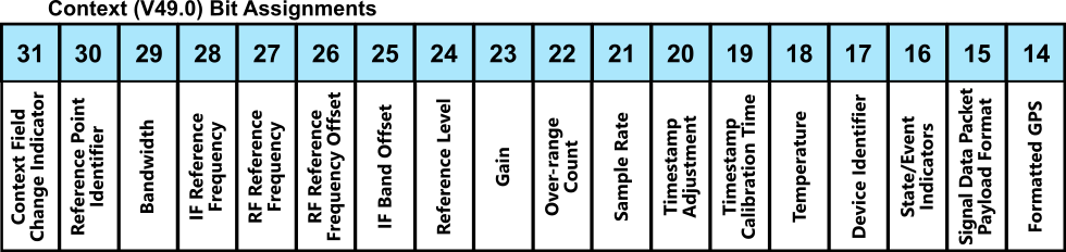
Context Packets
The VSA software looks for information in the Context packet to be able to process and show data correctly. See Table 9.1-1 of the VITA 49 standard to see the full Context/Command Indicator Field (CIF Common Intermediate Format: A video image format using 352 horizontal pixels and 288 vertical lines. The format is adopted in multimedia communication standards.) matrix and bit assignments.
For VITA 49.2, Signal Data Packet Payload Format (Bit 15) needs to be set to 1.
For both VITA 49.2 and ODI, the VSA software acts on CIF 0 fields as described in the following table:
| Bit | CIF0 | Conditions | |
|
29 |
Bandwidth |
See Bit 21 Sample Rate. If set to 1 then the value of the Bandwidth field is used as the maximum span in VSA. Note: A value of 0 is not supported for the Bandwidth field. |
|
|
27 |
RF Radio Frequency: A generic term for radio-based technologies, operating between the Low Frequency range (30k Hz) and the Extra High Frequency range (300 GHz). Reference Frequency |
If set to 1, then use it as the input center in VSA. Input center = RF Reference Frequency + RF Reference Frequency Offset + IF Band Offset |
|
|
26 |
RF Reference Frequency Offset |
If set to 1, then use in determining the input center in VSA (see RF Reference Frequency). |
|
|
25 |
IF Band Offset |
If set to 1, then include the value of the IF Band Offset field in determining the input center in VSA (see RF Reference Frequency). |
|
|
24 |
Reference Level |
If set to 1, use it in VSA to calculate the input range and scaling factor if it's normalized data. |
|
|
21 |
Sample Rate |
If set to 1, use it directly in VSA. If set to 0, but if Bandwidth is set to 1, use Bandwidth to make the best guess. If both Sample Rate and Bandwidth are set to 0, use default value 1 as Sample Rate. |
|
|
16 |
State/Event Indicators |
If set to 1 then use the State/Event Indicators field (see the State and Event Indicators table for how VSA uses each of those bits). Note: If a trailer is present in the signal data packet then any indicator bits there that are enabled will be used instead of the equivalent ones in the context packet. |
Changes in context packet fields that affect the Input Center calculation in VSA, Sample Rate, Bandwidth, or scaling of the data are handled as follows:
-
The VSA software will automatically re-initialize the measurement in VSA the next time a measurement is made to update to the new information from the context packet.
-
The center frequency in the VSA software will be updated based upon the newly computed Input Center from the new context packet information. But, the offset of the center frequency in the VSA measurement relative to the computed Input Center before the change occurs will be preserved when updating it based upon the new context packet information. This way if any software tuning had been done in the VSA software then that software tuning offset should be preserved relative to the change in the underlying Input Center computed from the context packet.
-
The span in VSA will either be preserved or changed to match the new Bandwidth from the context packet. If the span in VSA was less than the previous context packet Bandwidth field then it will be preserved. If the span was equal to the previous context packet Bandwidth field then it will be updated to be equal to the new context packet's Bandwidth field.
-
State and Event Indicators
| Indicator Bit Position | State/Event Indicator | Usage in VSA | |
|
19 |
Calibrated Time Indicator |
Not currently used |
|
|
18 |
Valid Data Indicator |
If the corresponding enabled bit 30 is 1 and this bit is 0 then a DATA? will be indicated in the traces with a reason indicating that this bit was 0. Note: This is only supported for the streaming usage in VSA and not when recalling VITA 49 recording files. |
|
|
17 |
Reference Lock Indicator |
If the corresponding enabled bit 29 is 1 and this bit is 0 then the status bar in the VSA application window will indicate an UNLOCKED condition for the frequency reference. Note: This is only supported for the streaming usage in VSA and not when recalling VITA 49 recording files. |
|
|
16 |
Not currently used |
||
|
15 |
Detected Signal Indicator |
Not currently used |
|
|
14 |
Spectral Inversion Indicator |
If the corresponding enabled bit 26 is 1 and this bit is 1 then the VSA software will conjugate the IQ time domain data to reverse the spectral inversion so that the data when viewed and analyzed in VSA is equivalent to what is at the reference point (since this bit indicates whether the spectrum is inverted relative to the reference point). Users can use the Mirror Frequency functionality in VSA to undo this if desired. |
|
|
13 |
Over-range Indicator |
If the corresponding enabled bit 25 is 1 and this bit is 1 then the VSA software will show the indication as follows: When streaming, the OV (overload) indication will show in the traces. When doing playback from a recalled recording, it will be shown in the Info tab of the Recording dialog. |
|
|
12 |
Sample Loss Indicator |
If the corresponding enabled bit 24 is 1 and this bit is 1 then the VSA software will show a DATA? in the traces with a reason indicating that this bit was 0. Note: This is only supported for the streaming usage in VSA and not when recalling VITA 49 recording files. |
Other Considerations
- Data files must have at least one context packet and one data packet containing time domain data in the file.
- All packets are contiguous in time (no gaps).
- Context packet type should be distinct (no two context packets with different values exist in the same file, or the first context packet will be used).
- Single channel data only.
- The payload size must be the same for all data packets, except if sampleFrameIndicator in the trailer part of the last packet is defined as FinalPacket.
See Also