TD-SCDMA Modulation Overview
Principles of TD-SCDMA (Time Division Synchronous Code Domain Multiple Access)
TD-SCDMA (Time Division Synchronous Code Domain Multiple Access) is a multiple access technology, which is a combination of code division multiple access (CDMA Code Division Multiple Access: One of several digital wireless transmission methods in which signals are encoded using a specific pseudo-random sequence, or code, to define a communication channel. A receiver, knowing the code, can use it to decode the received signal in the presence of other signals in the channel. This is one of several "spread spectrum" techniques, which allows multiple users to share the same radio frequency spectrum by assigning each active user an unique code. CDMA offers improved spectral efficiency over analog transmission in that it allows for greater frequency reuse. Other characteristics of CDMA systems reduce dropped calls, increase battery life and offer more secure transmission. See also IS-95.) and time division multiple access (TDMA Time Division Multiple Access: A technology for digital transmission of radio signals between, for example, a mobile telephone and a radio base station. In TDMA, the frequency band is split into a number of channels which in turn are stacked into short time units so that several calls can share a single channel without interfering with one another. Networks using TDMA assign 6 timeslots for each frequency channel. TDMA is also the name of a digital technology based on the IS-136 standard. TDMA is the current designation for what was formerly known as D-AMPS.). TDD Time Division Duplex: A duplexing technique dividing a radio channel in time to allow downlink operation during part of the frame period and uplink operation in the remainder of the frame period. (Time Division Duplexing) is used in TD-SCDMA to separate the uplink and downlink. The frame length (or the TDD interval) of TD-SCDMA is 5 ms and the whole frame is divided into downlink and uplink by the two switching points. Both the uplink and downlink periods are divided into timeslots. The total number of timeslots is 7. The ratio for uplink/downlink can be reconfigured to provide symmetric or asymmetric data services. Within each timeslot, the CDMA is implemented with the maximum spreading factor of 16. In other words, up to 16 code channels can be within the same timeslot.
In TD-SCDMA the CDMA chip rate is 1.28 Mcps Mega Chip Per Second: A measure of the number of bits (chips) per second in the spreading sequence of direct sequence spreading code. and each carrier occupies 1.6 MHz Megahertz: A unit of frequency equal to one million hertz or cycles per second. bandwidth.
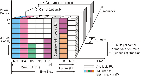
Resource Unit (RU)
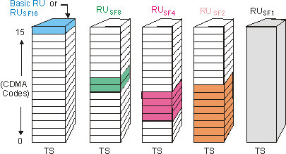
Compared with GSM Global System for Mobile Communications: Originally developed as a pan-European standard for digital mobile telephony, GSM has become the world’s most widely used mobile system. It is used on the 900 MHz and 1800 MHz frequencies in Europe, Asia and Australia, and the 1900 MHz frequency in North America and Latin America., the smallest unit in the frame of TD-SCDMA is the basic Resource Unit (RU), which is defined by frequency, timeslot (TS Technical Specification), and code channel with spreading factor. The basic RU uses a spreading factor of 16. Notice that halving the Spreading Factor doubles the number of RU's.
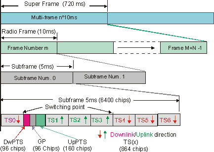
TD-SCDMA Frame Structure at 1.28Mcps
All physical channels utilize a three-layer structure: Super frame, Radio frame, and Sub-frame.
-
Timeslot (TS): 7 total timeslots (0 through 6), 864 chips in duration.
-
Uplink (UL Up Link (reverse link: from cell phone to base station)) and Downlink (DL Down Link (forward link: from base station to cell phone)) timeslots are separated by switching points. There are two switching points per sub-frame. One switch point is fixed at the end of TS0, the other may be moved to the end of any other timeslot.
-
TS0 is always allocated as downlink.
-
TS1 is always allocated as uplink.
-
Three special Timeslots (TS):
-
DwPTS: Downlink Pilot Timeslot, 96 chips
-
UpPTS: Uplink Pilot Timeslot, 160 chips.
-
GP: main Guard Period for TDD operation, 96 chips
-
-
The system supports symmetric and asymmetric mode by properly configuring the number of DL and UL timeslots.
A physical channel is defined by frequency, timeslot, channelization code, burst type, and Radio Frame allocation. The scrambling code and the basic midamble code are broadcast and may be constant within a cell. When a physical channel is established, a start frame is given. The physical channels can either be of infinite duration or finite duration defined for the given allocation.
TD-SCDMA Burst Structure
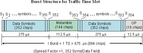
A physical channel in TDD is a burst, which is transmitted in a particular timeslot within allocated Radio Frames. The allocation can be continuous or discontinuous. A burst is the combination of two data symbol fields, a midamble, and a guard period. The duration of a burst is one timeslot. Several bursts can be transmitted at the same time from one transmitter. In this case, the data part must use different OVSF Orthogonal Variable Spreading Factor (codes) (orthogonal variable spreading factor) channelization codes, but the same scrambling code. The midamble part has to use the same basic midamble code, but can use different midamble shifts.
The data part of the burst is spread with a combination of channelization code and scrambling code. The channelization code is an OVSF code, which can have a spreading factor of 1, 2, 4, 8 or 16. The data rate of the physical channel depends upon the used OVSF code and spreading factor.
The following figure shows a typical TD-SCDMA Frame Structure for a traffic timeslot including the symbol numbering convention. It assumes a Spreading Factor of 1 and Data fields containing 352 symbols each.
-
Timeslot (Burst):
-
Each timeslot is 675 us, 864 chips.
-
Channel estimation for uplink and downlink.
-
Power measurements.
-
Maintaining uplink synchronization.
-
-
-
Data Symbols:
-
Two Data fields at 352 chips each. The number of symbols depend on the Spreading Factor. May include optional TPC Transmit Power Control power control bits, TFCI Transport Format Combination Indicator bits, and uplink SS (synchronization shift) synchronization bits.
-
Channel estimation for uplink and downlink.
-
Power measurements.
-
Maintaining uplink synchronization.
-
-
-
GP (Guard Period):
-
16 chips, used to avoid timeslot multi-path interference
-
Channel estimation for uplink and downlink.
-
Power measurements.
-
Maintaining uplink synchronization.
-
-
-
Midamble field:
-
144 chips formed from one of 128 basic midamble sequences with 128 chips each.
-
The 128 sequences are divided into 32 groups corresponding to 32 SYNC-DL codes.
-
Each group consists of 4 different basic midamble sequences.
-
Basic midamble sequences are used as training sequences for:
-
Channel estimation for uplink and downlink.
-
Power measurements.
-
Maintaining uplink synchronization.
-
-
DwPTS: Downlink Pilot Timeslot

-
Used for DL synchronization and cell initial search.
-
96 chip length: 32 chips for GP, 64 synchronization.
-
The GP used to avoid interference between the last DL traffic TS and the DL sync pilot burst.
-
32 different SYNC-DL group codes, used to distinguish base stations.
-
Transmitted radially in all direction with no beam forming capability.
UpPTS: Uplink Pilot Timeslot

-
Used for UL initial synchronization, random access, and measurement for adjacent cell handoff.
-
160 chip length: 128 for SYNC, 32 for GP
-
The GP fields are used to separate the UL pilot from the traffic UL timeslot.
-
There are 256 different SYNC codes, which can be divided into 32 groups and each group includes 8 different SYNC codes, i.e., each base station has 8 different SYNC codes.
-
BTSC gets initial beam forming parameters from the UL terminal signal.
Code/ID Allocation (see Code/ID Tab - TD-SCDMA Demod Properties)
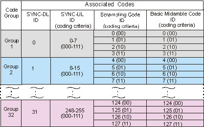
There are 32 possible code groups and 32 SYNC-DL sequences. Each SYNC-DL code corresponds to a group of 4 different basic midamble codes for a total of 128 non-overlapping midamble codes. The basic midamble code divided by 4 determines the SYNC-DL code number. The same basic midamble code is used throughout the frame and is associated with a corresponding scramble code (128 total).
Each code group associates 8 different SYNC-UL codes per code group for a total of 256 different SYNC-UL code sequences (32 * 8).
This table shows the relationship between the SYNC-DL and SYNC-UL sequences, the scrambling codes and the midamble codes for each code group.
-
: Downlink Pilot Synchronization is used for DL synchronization and cell initial search. There are 32 different SYNC-DL group codes, which are used to distinguish base stations.
-
: Uplink Pilot Synchronization (UpPTS) is used for UL initial synchronization, random access, and measurement for adjacent cell handoff. There are 256 different SYNC codes, which can be divided into 32 groups and each group includes 8 different SYNC codes, i.e., each base station has 8 different SYNC codes.
-
: Scrambling codes are cell specific and are used to identify separate cells. There are 128 different scrambling codes, which are associated with a corresponding basic midamble code.
-
Basic Midamble code ID's are training sequences for uplink and downlink channel estimation, power measurements and maintaining uplink synchronization. There are 128 different sequences divided into 32 groups corresponding to 32 SYNC-DL codes. Each group consists of 4 different basic midamble sequences, i.e. each BS Base Station - The equipment on the network side of a wireless communications link. The base station contains the tower, antennas and radio equipment needed to allow wireless communications devices to connect with the network. has 4 different midambles.
Modulation of the SYNC-DL
The SYNC-DL sequence are modulated with respect to the midamble in timeslot 0.
Four consecutive phases (phase quadruple) of the SYNC-DL are used to indicate the presence of the P-CCPCH Common Control Physical Channel (Primary Common Control Channel) in the following 4 sub-frames. In case the presence of a P-CCPCH is indicated, the next following sub-frame is the first sub-frame of the interleaving period. As QPSK Quadrature phase shift keying is used for the modulation of the SYNC-DL, the phases 135, 45, 225, 135 and 315, 225, 315, 45 are used.
The total number of phase quadruples is 2 (S1 and S2). A quadruple always starts with an even system frame number ((SFN System Frame Number mod 2) = 0).
|
Table: Sequence for the phase modulation for the SYNC-DL |
||
|---|---|---|
|
Name |
Phase Quadruple |
Meaning |
|
S1 |
135, 45, 225, 135 |
There is a P-CCPCH in the next four frames. |
|
S2 |
315, 225, 315, 45 |
There is no P-CCPCH in the next four frames. |
