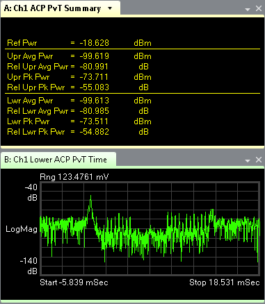
ACP PvT Summary (TEDS)
(Adjacent Channel Power Power versus Time Summary) shows the adjacent channel powers for both the upper and lower channels.

If the trace is blank and NO DATA appears in the upper-right corner or if the trace is blinking between a display and NO DATA, there is a problem with the VSA setup or the signal input. Check the slot format, channel bandwidth and modulation type in the TEDS Demodulation Properties dialog box.
The following are parameters for ACP Adjacent Channel Power: The power from a modulated communications channel that leaks into an adjacent channel. This leakage is usually specified as a ratio to the power in the main channel, but is sometimes an absolute power. PvT Summary:
|
Parameter |
Description |
|---|---|
|
Ref Pwr |
Average power of all sync and pilot symbols. See Comp Error Summary. |
|
Upr Avg Pwr |
Average power (dBm deciBels referenced to a milliWatt: dB relative to 1 milliwatt dissipated in the nominal input impedance of the analyzer) of the upper adjacent channel. |
|
Rel Upr Avg Pwr |
Average power of the upper adjacent channel relative to the reference power (Ref Pwr). |
|
Upr Pk Pwr |
Peak power (dBm) of the upper adjacent channel. |
|
Rel Upr Pk Pwr |
Peak power of the upper adjacent channel relative to the reference power (Ref Pwr). |
|
Lwr Avg Pwr |
Average power (dBm) of the lower adjacent channel. |
|
Rel Lwr Avg Pwr |
Average power of the lower adjacent channel relative to the reference power (Ref Pwr). |
|
Lwr Pk Pwr |
Peak power (dBm) of the lower adjacent channel. |
|
Rel Lwr Pk Pwr |
Peak power of the lower adjacent channel relative to the reference power (Ref Pwr). |
See Also
