24Pulse Generator Mode – Option 357 Under certain conditions, Battery saver mode is not permitted when using Pulse Generator Option 357, because battery saver mode would interrupt the source output signal. When using Pulse Generator Option 357 with the RF Output ON, normal periodic power saving maneuvers used by Battery Saver mode and Smart Power Management are disabled, to avoid interrupting the source output signal. Turning RF Output OFF will allow power management to resume normal operation.
Option 357 enables the RF signal generator output from port 1 to support pulse and analog (AM, FM) modulation. Source power level control to –90 dBm enables testing of receiver sensitivity. The pulse source supports 4 pulse types, continuous AM and FM, and the ability to create and generate pulse sequences. The FieldFox’s Source Sync Trigger OUT, which is synchronized with the RF pulse output, can be input to an oscilloscope trigger input to provide triggering for very low level sensitivity measurements. Refer to “Pulse Generator Settings” on page 657.
Calibration of the source is required for accurate receiver sensitivity testing. Refer to “How to make Pulse Generator Measurements” on page 657, “How to do a Single Point Frequency Calibration” on page 679, and “How to do Cable Calibration Measurements” on page 676.
Full access to all features of Option 357 is available even without a Pulse Generator Calibration for power levels as low as -60 dBm. In this scenario, the cal indicators display “Default Power” on the screen. Refer to Figure 3 on page 655.
When the CW frequency is calibrated, the cal indicators display “Calibrated Power” on the screen. Refer to Figure 1 on page 654 for an example display. The power level can be set below -60 dBm when using the calibrated CW frequency.
If the CW frequency is not calibrated, the cal indicators display “Default Power” on the screen. When the power level is set to below -60 dBm at the non-calibrated CW frequency, the screen will show “THIS POWER NOT CALIBRATED”. Refer to Figure 2 on page 654 for an example display. Calibration for the CW frequency is required for power levels below -60dBm. See “How to do a Single Point Frequency Calibration” (page 679).
Figure 1 CW = 10.1 GHz is Calibrated and Power Level Below -60 dBm
Figure 2 CW = 10 GHz Not Calibrated and Power Level Below -60 dBm
Figure 3 Pulse Generator Display and Annotation Overview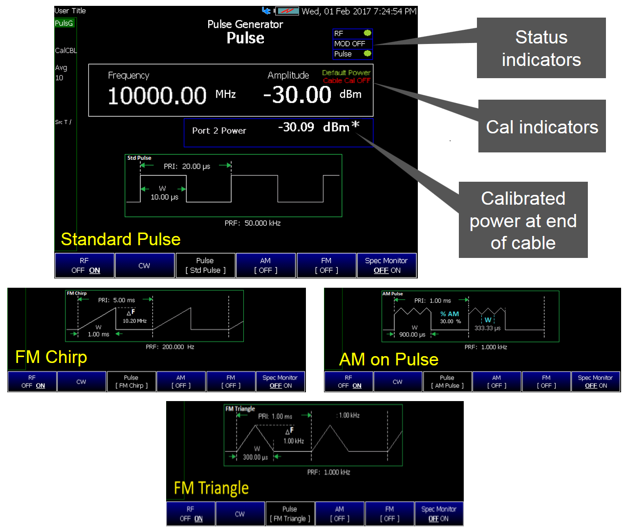
The graphic above shows an overview of the Pulse generator display with a sample of the pulse generation types. Some of the features included with the FieldFox Pulse Generator Mode are discussed in detail in the following documents:
Additional information:
For additional background on some of the features mentioned in this chapter, refer to the Preliminary Documentation Pulse Generator User Guide.
In this Chapter
—“Using the Calibration Wizard, Recall Cal, and Amplitude Alignment Softkeys” on page 674 |
—“How to do a Single Point Frequency Calibration” on page 679 |
Select Pulse Generator Mode before making any setting in this chapter.
A calibration is required, before using the pulse generator. Refer to the “Making Calibration Measurements” on page 674.
In this Section
How to select Pulse Generator Mode
—Press Mode_
—Then More, if your FieldFox contains more than five measurement modes.
—Then More, if your FieldFox contains more than ten measurement modes.
—Then Pulse Generator.
How to make Pulse Generator Measurements
See also, “Modifying Pulse Type Parameters” on page 659.
Before starting the following are recommended (refer to Figure 4 on page 658):
—Keysight 11667C 2-resistor power splitter connected to port 2

—Short low loss jumper cable or adapter to connect port 1 to the input of the splitter
—Adapters (miscellaneous) as needed to connect the cables
—50 ohm load to terminate the open splitter arm during calibration
Figure 4 Cal Wizard "Prepare for calibration..." and "Connect power splitter..." Screen
1.Press Preset then Preset (Factory) to return the FieldFox to the default settings.
2.Then Mode
—Then More, if your FieldFox contains more than five measurement modes.
—Then More, if your FieldFox contains more than ten measurement modes.
—Then Pulse Generator.
3.Press CW
4.Leave the rest of the settings in their default values.
5.Press Cal 5
6.Then Calibration Wizard
7.Follow the Calibration Wizard prompts and then Done.
8. Disconnect any components or adapters that should not be measured and connect the DUT.
Modifying Pulse Type Parameters
The pulse generation method defaults to CW measurement on with RF, MODulation, Pulse, and SA measurement monitor (Spec Monitor) OFF.
—Press Measure 1
—Then choose from the following:
—RF OFF ON Enables Port 1 RF source. Also, enables the RF source graphics and annotation. Default is RF OFF.
—CW Continuous Wave (default). CW is disabled when a Pulse menu choice is enabled.
—Pulse opens a menu of pulse softkey types.
Then press one of the following:
——Std Pulse sets the pulse type to standard pulse.
——FM Chirp sets the pulse to type FM chirp. FM chirps cannot span across band crossings. Refer to “FM Deviation Limits (Hz)” on page 680.
——FM Triangle sets the pulse type to FM triangle.
——AM Pulse sets the pulse type to AM pulse.
——Sequence enables you to input a list of different pulse types into a Pulse Sequence table. Refer to “How to Setup a pulse sequence table”.
—AM opens a menu of amplitude modulation types.
Then press one of the following:
——OFF disable amplitude modulation.
——AM Triangle enables AM triangle modulation.
——AM Sine enables AM sine modulation.
—FM opens a menu of continuous frequency modulation types.
Then press one of the following:
——OFF disable frequency modulation.
——Sawtooth enables FM sawtooth modulation.
——FM Triangle enables FM triangle modulation.
——FM Sine enables FM sine modulation.
——FSK enables FM Frequency Shift Keying (FSK) modulation.
——BPSK enables FM Binary Phase Shift Keying (BPSK) modulation.
—Spec Monitor (default == OFF) enables the SA monitor that displays the pulse signal’s RF signal source frequency and receiver offset.
How to Setup a pulse sequence table
This section will guide you through the creation of a pulse sequence table. The Sequence softkey menu enables you to choose different pulse types and to modify the pulse sequence behavior via the pulse sequence table. Some pulse sequence parameters are only available for editing for specific pulse types (e.g., Mod Width is only active for editing when AM Pulse is the selected Pulse Type).
This section contains the following:
—“Pulse Sequence Table Selection”
—“Sequence Table Set Up Example”
Pulse Sequence Table Selection
The section provides an overview of the Pulse Sequence table’s softkey menus. Refer to Figure 5 on page 662 and Figure 6 on page 662.
—Press Measure 1
—Then Pulse
—Then Sequence
—Then Meas Setup 4 opens a menu of pulse sequence table softkeys:.
——Pulse Sequence Table and select one of the following:
——Selection then select one of the following:
On (default) | All rows are on in the sequence table and all will be continually played as a pulse train. | |
Continuous | The currently selected pulse plays continuously and all other pulses (rows) are off. | |
Off | Disables the current selected pulse. |
—Optional: When you move the  arrow keys or the knob, the Edit softkey is displayed in lieu of the Selection softkey:
Edit enables editing of each of the currently selected pulse row’s column parameters.
——Next Page moves the cursor to the top of the next page, if the table extends onto the next page or to the end of the current table, if table is on one page.
——Next Up moves the cursor to the top row of the previous page.
——Add Row adds a new pulse/row.
——Delete/Clear and select one of the following:
Delete Row | removes the currently selected pulse row from the sequence table. IMPORTANT! No opportunity to undo. | |
Clear All | opens a menu that enables you to clear/delete the sequence table. Then confirm the selection by: | |
Back | cancels Delete/Clear and returns to the previous menu. |
—Then Freq /Dist opens the frequency menu softkeys.
——Then choose Freq and use the arrow keys or the knob to edit the frequency being measured on the display.
—Then Scale/ Amptd opens the amplitude menu softkeys.
——Then choose Amplitude and use the arrow keys or the knob to edit the amplitude being measured on the display.
Figure 5 Pulse Sequence Table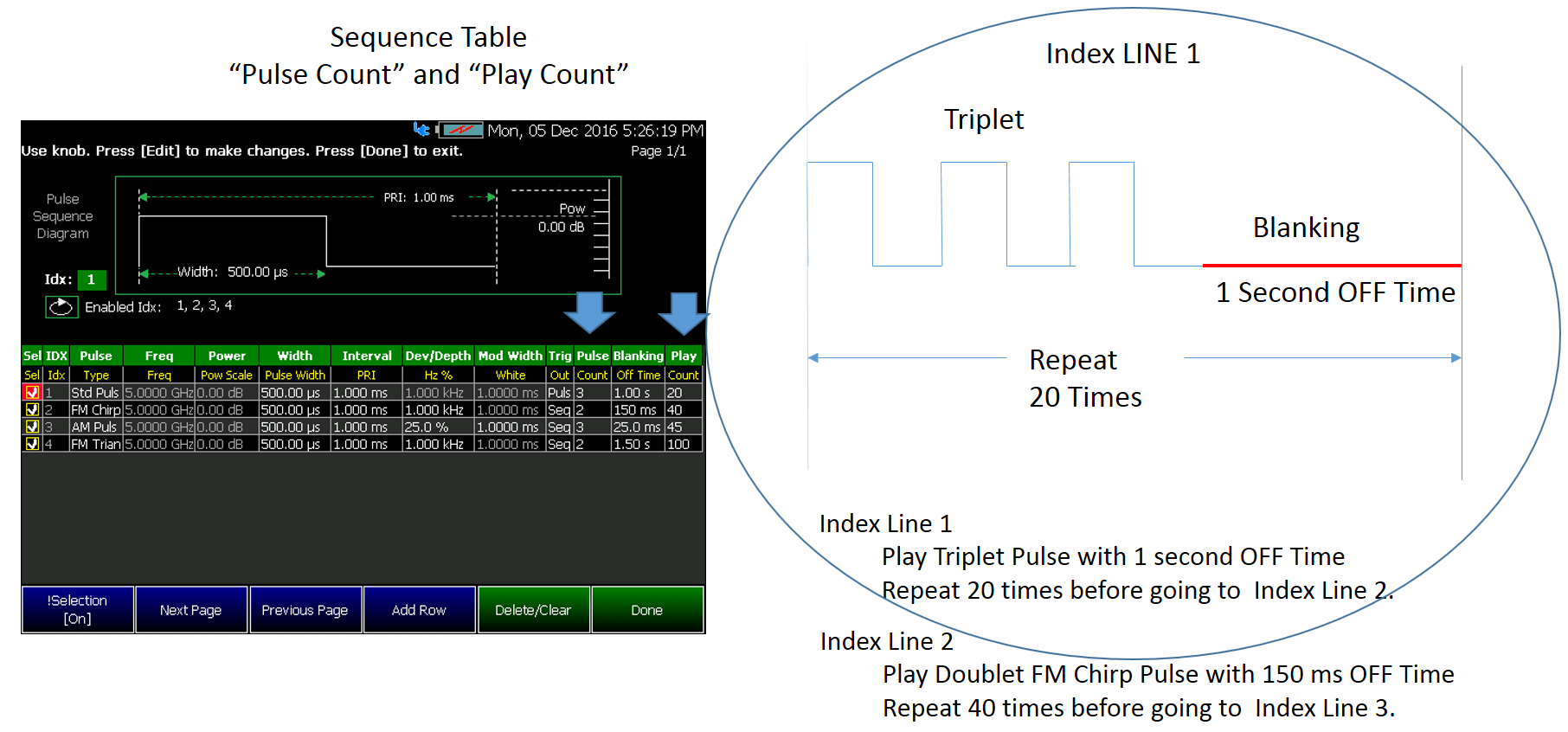
Figure 6 Editing a Pulse Sequence Table
—Press Measure 1
—Then Pulse
—Then Sequence
—Then Meas Setup 4 opens a menu of pulse sequence table softkeys.
——Then Pulse Sequence Table
——Then in the Pulse Sequence Table, use the arrow keys or the knob to edit the Selection (Sel—disable/enable sequences to play), Pulse Type (Type—change the pulse type), Pulse Width, Interval (PRI), Dev/Depth (Hz %), Mod Width (Width), Trig (Out), Trig (Delay), Pulse (Count), Blanking (Off Time), and Play (Count).
——When you have finished editing the Pulse Sequence Table:
Then Save Pulse List (pulse sequence files can only be saved as *.xml files).
—Then Freq /Dist opens the frequency menu softkeys.
——Then choose Freq and use the arrow keys, the knob, or the numeric keypad to set the frequency of the pulse sequence.
—Then Scale/ Amptd opens the amplitude menu softkeys.
——Then Amplitude use the arrow keys, the knob, or the numeric keypad to set the power level of the output pulse sequence.
| To verify peak power level amplitude accuracy, after a test has been completed at the frequency of interest, select CW and read the Port 2 power. |
Figure 7 Pulse train plays continuously with per pulse trigger out
Figure 8 Chirped pulse plays continuously with trigger out every pulse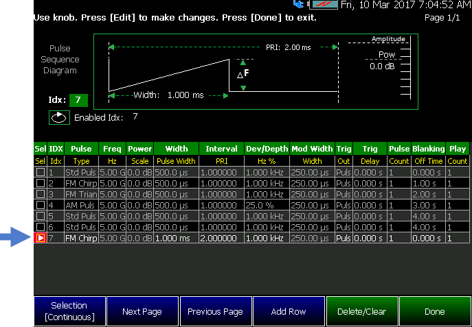
Figure 9 FM triangle doublet with 10.0 ms blanking (OFF time) continuously with trigger out every sequence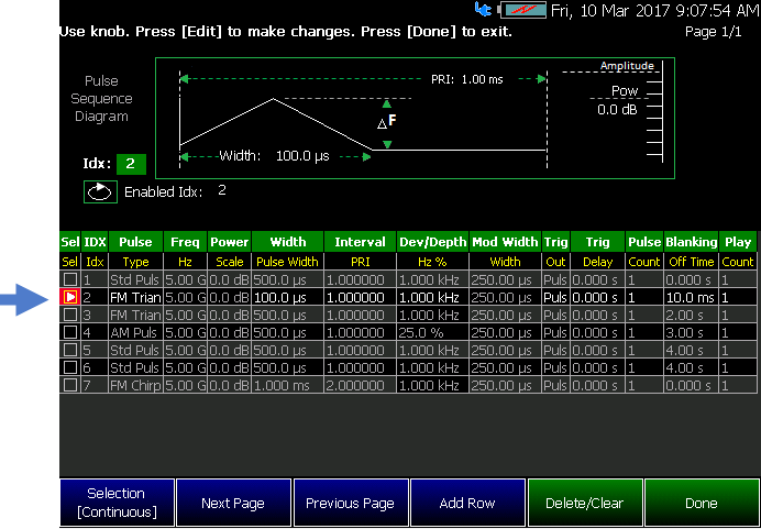
Figure 10 FM triangle doublet with 2.0 s blanking (OFF time) continuously with trigger out every pulse
Figure 11 AM triplet with 3.5 s blanking (OFF time) plays continuously with trigger out OFF
Figure 12 Pulse Sequence Blanking (OFF Time) 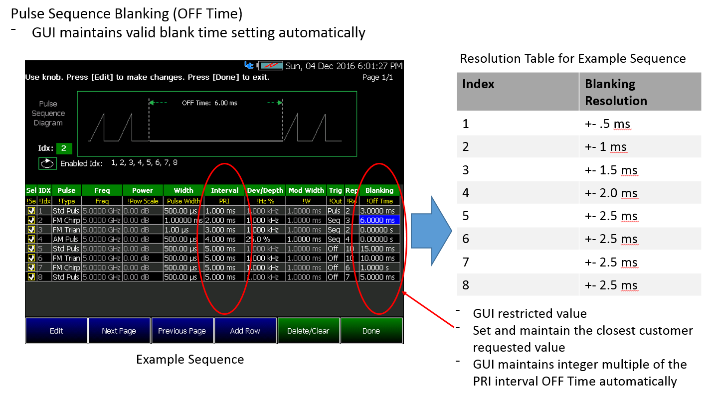
How to Set the Pulse Measurement Setup Parameters
This section provides details how to set up each type of Pulse Generator type. Measurement setup menu available softkeys depend on the selected pulse type.
After selecting your pulse type, the measurement parameters need to be selected for your pulse measurement. Refer to “Pulse Generator Settings” on page 657.
This section contains the following topics:
—Selecting a pulse generator type:
—“Measure Setup Settings for Pulse Generator Types” on page 666
—Selecting a modulation waveform (CW) type:
—“Measurement Setup Settings Pulse Generator Modulation Waveform (CW) Types” on page 670
Measure Setup Settings for Pulse Generator Types
—Press Meas Setup 4
—Then choose from the following:
—PRF sets the pulse repetition frequency. Not available with AM pulse. The default duty cycle is 30%. Additionally, whenever a pulse width is changed to a value that is incompatible with the current pulse period setting, the pulse period is set to a 30% duty cycle with the new pulse width. Also, when a pulse period is changed to a value that is incompatible with the current pulse width, the pulse width is changed to give a 30% duty cycle with the new pulse period. The duty cycle (on time) cannot be directly measured, but can be calculated via the following equation: Duty cycle = [(Pulse width (seconds) * PRF (pulse repetition frequency)) * 100]
—PRI sets the pulse repetition interval for the time from the start of one pulse to the start of the next pulse. The PRI must be at least 2.33 ms longer than the pulse width (e.g., if the pulse width = 1.000 ms, then the PRI must be 1.000 ms + 2.330 ms or 3.330 ms).
—Pulse Width sets the 50% pulse width (1.000 ms to 1.00s, default varies with pulse type selected). The minimum useful Pulse Width duration depends on the frequency setting, the FM deviation, and the pulse type.
For recommended setting limits, refer to FM Deviation softkey below. See also Table 12-1 on page 669 and “FM Deviation Limits (Hz)” on page 680.
| The default duty cycle is 30%. Additionally, whenever a pulse width is changed to a value that is incompatible with the current pulse period setting, the pulse period is set to a 30% duty cycle with the new pulse width. Also, when a pulse period is changed to a value that is incompatible with the current pulse width, the pulse width is changed to give a 30% duty cycle with the new pulse period. A pulse’s duty cycle cannot be directly measured, but can be calculated via the following equation: Duty cycle = [(Pulse width (seconds) * PRF (pulse repetition frequency)) * 100] |
—Mod Width sets the modulation width (50.000 ms to 10s, default is 250.000 ms). Only available with AM pulse. Modulation width is coupled to other pulse settings (e.g., Frequency). See also Table 12-1 on page 669.
—Depth sets the AM depth (0.000 to 100.0%, default is 25.00%. Only available with AM pulse.
—FM Deviation sets the FM deviation. Refer to Table 12-1 on page 669. See also, Pulse Width softkey description above and “FM Deviation Limits (Hz)” on page 680, and to Table 1 on page 681.
| You are able to set the FM deviation to a particular maximum value for the current coupled settings (e.g., pulse type, carrier frequency), if your FM deviation is set too high for the pulse width, pulse type, or other settings, the FieldFox displays an error message similar to the example below. Example: FM Deviation request exceeds 1% FM overrange @5000 MHz band crossing. |
—Trig Delay sets the trigger delay. (Calculated by (–1 x the PRI to +1 x the PRI), default is 0.000 s).
| Trigger delay can be positive or negative. The magnitude of trigger delay cannot exceed the PRI (pulse repetition interval). PRI = 1.00 ms Trigger delay can be set anywhere from -1.00 ms to +1.00 ms for a PRI setting of 1.00 ms.
Trigger delay can be set anywhere from -3.5 ms to +3.5 ms for a PRI setting of 3.5 ms. |
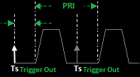
—Export Pulse to Sequence Exports the current pulse to the last pulse sequence table in memory and displays "Pulse sequence list updated". Refer to “How to Setup a pulse sequence table” on page 660.
Type of Signal (Pulsed or Non-Pulsed) | Maximum FM Deviation | Maximum FM Rate | Minimum Pulse Width | Minimum Modulation Width | Maximum AM Rate | Maximum AM Depth | Minimum Time Interval |
|---|---|---|---|---|---|---|---|
Pulsed | |||||||
AM Pulse | -- | -- | 50 ms | 50 ms | -- | 75% | -- |
FM Chirp / FM Triangle | 10 MHz | -- | 1 ms | -- | -- | -- | -- |
1 MHz | -- | 500 ms | -- | -- | -- | -- | |
100 kHz | -- | 250 ms | -- | -- | -- | -- | |
≤10 kHz | -- | 100 ms | -- | -- | -- | -- | |
Non-Pulsed | |||||||
AM Triangle / AM Sine | -- | -- | -- | -- | 20 kHz | 75% | -- |
FM Triangle / | 10 MHz | 1 kHz | -- | -- | -- | -- | -- |
1 MHz | 2 kHz | -- | -- | -- | -- | -- | |
100 kHz | 4 kHz | -- | -- | -- | -- | -- | |
≤10 kHz | 10 kHz | -- | -- | -- | -- | -- | |
FM Sawtooth | ≤100 kHz | 10 kHz | -- | -- | -- | -- | -- |
FSK | ≤100 kHz | -- | -- | -- | -- | -- | 100 ms |
BPSK | -- | -- | -- | -- | -- | -- | 100 ns |
a.Measurement quality may be impacted, if the recommended modulation values are exceeded.
Measurement Setup Settings Pulse Generator Modulation Waveform (CW) Types
—Press Meas Setup 4
—If AM Triangle or AM Sine –
Then choose from the following:
—AM Rate sets the AM rate. (0 to 50 kHz, default is 1 kHz) While you are able to set the AM Rate up to 50 kHz. The maximum recommended value is 15 kHz. Setting AM Rate to greater than 15 kHz may degrade your measurements.
—AM Depth sets the AM depth (0 to 100%, default is 25%)
—If FM Sine or FM Triangle or Sawtooth –
Then choose from the following:
—FM Rate sets the FM rate. (0 to 50 kHz, default is 1 kHz). For the recommended maximum frequency rates, refer to Table 12-1 on page 669.
—FM Deviation sets the FM modulation positive or negative deviation or total deviation. The highest and lowest frequencies must be within the same frequency band. Refer to Table 12-1 on page 669 and to “FM Deviation Limits (Hz)” on page 680, and to Table 1 on page 681. (default is 1kHz)
—If BPSK –
Then choose from the following:
—Time Interval1 sets the time duration of the first phase (1ns to 1s, default == 1ms).
—Time Interval2 sets the time duration of the second phase (1ns to 1s, default == 1ms) which is shifted by 180 deg from the first phase.
—If FSK –
Then choose from the following:
—Freq Index press to toggle between 1, 2, 3 and 4 to edit each frequency tone.
—Enable default == OFF except Freq Index == 1.
——ON enables the selected frequency tone.
——OFF disables the selected frequency tone.
—Deviation set the frequency deviation of the selected frequency tone.
—Time Interval set the time duration of the selected frequency tone. Freq Index == 1 represents the CW, therefore Enable is fixed to ON and Deviation is fixed at 0 Hz with no option for adjustment.
The following is an example showing 3-Tone FSK: F1 = 5GHz, F2 = 5GHz + 1kHz, F3 = 5GHz - 1kHz, and each frequency tone is activated for 1ms. Below are the corresponding entries:
—Sets CW frequency to 5 GHz in Pulse Generator mode.
—— Press Mode > More > More > Pulse Generator
—— Press Freq/Dist
—— Press Freq then enter 5GHz
—Sets the FSK parameters for a frequency tone, Deviation and Time Interval.
—— Press Measure 1 > FM > FSK
—— Press Meas Setup 4
—— Press Freq Index to toggle 1 to set frequency tone F1
—— Press Time Interval then enter 1ms
Figure 13 Meas Setup FSK setting for frequency tone F1 example
—— Press Freq Index to toggle 2 to set frequency tone F2
—— Press Enable to toggle ON
—— Press Deviation then enter 1kHz
—— Press Time Interval then enter 1ms
Figure 14 Meas Setup FSK setting for frequency tone F2 example
—— Press Freq Index to toggle 3 to set frequency tone F3
—— Press Enable to toggle ON
—— Press Deviation then enter -1kHz
—— Press Time Interval then enter 1ms
Figure 15 Meas Setup FSK setting for frequency tone F3 example
—— Press Freq Index to toggle 4 to disable the frequency tone
—— Press Enable to toggle OFF
Figure 16 Meas Setup FSK setting to disable frequency tone for Freq Index == 4 
—The graphic below shows the corresponding FSK entries sample above (the waveform is not to scale).
Figure 16-1 The graphic corresponding to 3-Tone FSK sample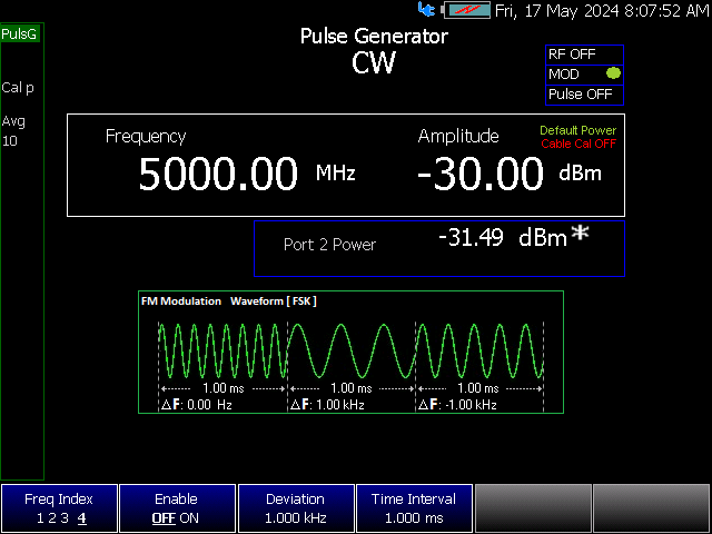
How to set Amplitude
Press Scale / Amptd. Then choose from the following:
—Amplitude sets the RF port power from -110 dBm to 10 dBm. (default is –30 dBm)
Freerun/RefOut and SSync/TrigOut Video allows you to select a trigger type.
Use the Sweep 3 hardkey to access the trigger type softkey.
—Trig Type [Freerun/RefOut] default is Freerun/RefOut.
—Freerun/RefOut sets the trigger to freerun. (This is the default setting when the RF is OFF. No signal is output at Ref/Trig Output SMB.)
—SSync/TrigOut uses the FieldFox’s side panel Ref/Trig Output SMB connector to output a trigger synchronized with the start of a RF pulse output or the falling edge of a pulse.
Pulse sequences can have positive or negative delay.
This trigger output can be input to a scope trigger input to provide triggering for very low level sensitivity measurements. (This is the default setting when the RF is ON.)
Making Calibration Measurements
Use this procedure to calibrate and store source, test cable, and single point calibrations in the FieldFox. Refer to Figure 19 on page 678 and Figure 20 on page 678.
In this Section
Using the Calibration Wizard, Recall Cal, and Amplitude Alignment Softkeys
—Press Cal 5
Then choose from the following
Calibration Wizard Softkey
Calibration Wizard takes you to the Calibration Wizard softkey menu, where you are guided through a source calibration with a power splitter, cables, and 50 ohm load that are connected from Port 1 to Port 2.
Follow the Calibration Wizard prompts.
Figure 17 Calibration Wizard: Pulse Generator Source Calibration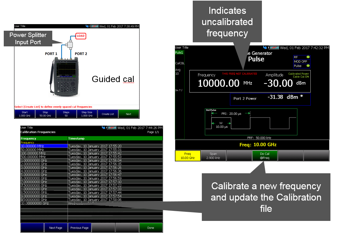
Recall Calibration Softkeys
—Recall Cal if a calibration has been previously stored in the current memory location, this menu enables you to recall a previously stored calibration file.
—View Cal if a calibration has been previously performed, this screen displays a table of the current calibration values for each frequency point and the time stamp for each calibrated frequency point.
Amplitude Alignment Softkeys
This is the same as InstAlign which operates in SA mode, to correct for Receiver drift over temperature and time. SA measurement applications monitor changes in internal temperature to trigger the need for an update to this alignment. After 1 degree C of temperature change, or 25 minutes, an alignment is deemed stale requiring an update. Until the update is performed, annotation indicating “questionable amplitude” is displayed AMPTD?. The alignment requires use of the internal source, which thus interrupts the integrity of the Pulse Generator’s RF Output.
| IMPORTANT! Pulse Generator mode handles the Amptd? condition differently than SA Mode. Setting the Amplitude Alignment may not correct the Amptd? condition, unless the RF is OFF or when changing frequencies. |
—Press Cal 5
—Then Amptd Alignment
—Then choose from the following:
—Auto (Default setting) Alignments are performed automatically when necessary at times when interrupting the users RF Output are deemed acceptable. In the Pulse Generator application, these times are restricted to either when the RF Output is OFF, or when the RF Source carrier frequency changes. If a needed alignment cannot be performed, the user is notified about questionable amplitude AMPTD?.
—OFF Alignments are not performed. The most recent alignment result is cleared. Only factory corrections are applied to SA Receiver measurements. Questionable amplitude AMPTD? is always displayed.
— Hold The alignment process is stopped, but the last alignment values are applied to subsequent sweeps.
—Amptd Align Now An alignment is performed immediately, thus updating (clearing) any questionable amplitude status. If the Mode was previously Off, it is changed to Hold.
Amptd? is annotated in the lower left corner of the FieldFox screen when amplitude alignment is questionable (because of time/temperature) and this setting is in Hold or OFF.
How to do Cable Calibration Measurements
Use this procedure to calibrate and store a test cable in the FieldFox. Refer to Figure 18 on page 677, Figure 20 on page 678, Figure 20 on page 678, and to “Using the Independent Marker” on page 678.
—Press Scale / Amptd
—Recall Cable recalls existing cable calibration corrections from the current memory location selected (i.e., FieldFox Internal, SD Card, or USB stick).
—Measure Cable takes you to a Cable Loss Measurement Wizard, where you can calibrate a cable connected from Port 1 to Port 2.
Follow the Cable Loss Measurement Wizard prompts. Refer to Figure 18 on page 677.
—View Corrections toggles a display on/off that enables you to view your cable’s loss.
—Apply Corrections applies the current cable corrections in memory. Cable Cal ON annotation is displayed.
—Save Cable opens the Create Filename display where you can name your file and saves the current cable being measured to the memory location selected (i.e., FieldFox Internal, SD Card, or USB stick). Cable Cal ON annotation is displayed. Refer to Figure 19.
Figure 18 Calibration Wizard: Pulse Generator Cable Loss Calibration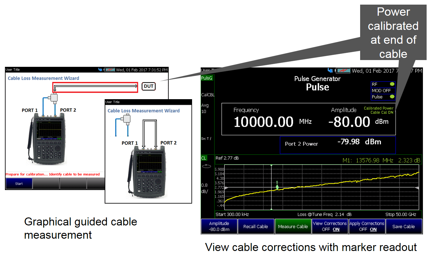
Figure 19 Cable Calibration Annotation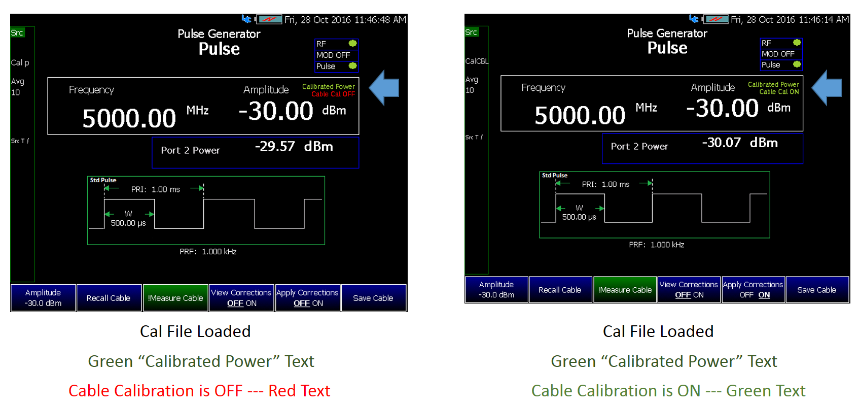
Figure 20 Verify Cable: [View Correction] Cable Loss Graph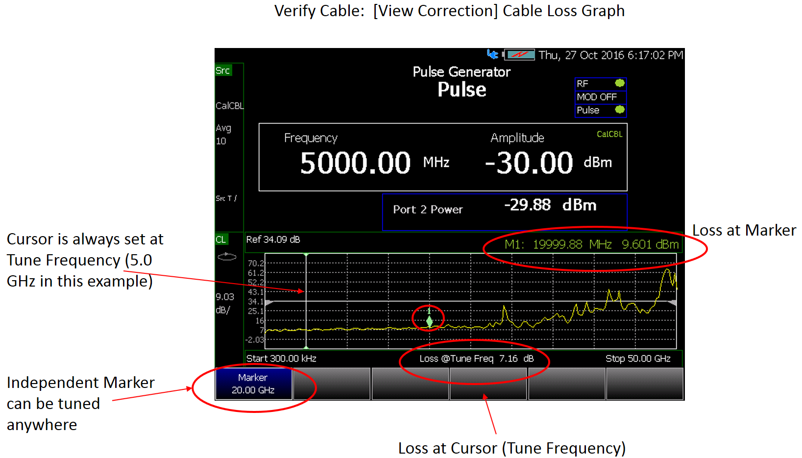
Use the FieldFox independent marker to measure the loss along the displayed cable trace.
—Press Marker and use the arrow keys, or knob to adjust the marker along the trace.
How to do a Single Point Frequency Calibration
After setting up your Frequency.
—Press Freq/Dist
—Then choose from the following:
—Press Do Cal @Freq to do a single frequency point calibration
— Follow the Calibration Wizard prompts.
FM Deviation Limits (Hz) Table 1 on page 681 shows the frequency values for N9915C and N9935C, other FieldFox models are similar, but the applicable frequency range varies.
Using FM Deviation Limits—Examples
—For 10 GHz tune frequency, customer may select positive FM deviation of +100 MHz (1%) above the band switch frequency at 10 GHz.
—For a 5 GHz tune frequency, you can select negative FM deviation of –2.525 GHz, since the lowest frequency for the band is 2.5 GHz, and the FM deviation limit is 1% below that value, or 2.475 GHz, giving a total deviation of 2.475 GHz - 5 GHz = –2.525 GHz.
—For mid band tune frequency at 7.5 GHz, customer can select anything up to +2.6 GHz / –2.55 GHz FM deviation.
Tune Frequency (Hz) | FM Lower Limit | FM Upper Limit | Worst Case Available % Deviation From Tune Frequency | N, Number Use For Maximum Deviation Setting |
|---|---|---|---|---|
1,870,001 - 2,929,600 | 1,851,301 | 2,958,896 | 1 | 1 |
2,929,601 - 5,859,300 | 2,900,305 | 5,917,893 | 1 | 2 |
5,859,301 - 6,340,000 | 5,800,708 | 6,403,400 | 1 | 4 |
6,340,001 - 11,718,700 | 6,276,601 | 11,835,887 | 1 | 8 |
11,718,701 - 23,437,500 | 11,601,514 | 23,671,875 | 1 | 16 |
23,437,501 - 46,485,000 | 23,203,126 | 46,949,850 | 1 | 32 |
46,485,001 - 93,360,000 | 46,020,151 | 94,293,600 | 1 | 64 |
93,360,001 - 187,110,000 | 92,426,401 | 188,981,100 | 1 | 128 |
187,110,001 - 374,610,000 | 185,238,901 | 378,356,100 | 1 | 256 |
374,610,001 - 749,610,000 | 370,863,901 | 757,106,100 | 1 | 512 |
749,610,001 - 1,499,610,000 | 742,113,901 | 1,514,606,100 | 1 | 1024 |
1,499,610,001 - 2,999,610,000 | 1,484,613,901 | 3,029,606,100 | 1 | 2048 |
2,999,610,001 - 5,999,610,000 | 2,969,613,901 | 6,059,606,100 | 1 | 4096 |
5,999,610,001 - 11,999,610,000 | 5,939,613,901 | 12,119,606,100 | 1 | 8192 |
Maximum Settable FM Deviation
For each FM type, whether it’s Pulse or Non-Pulse excluding BPSK, there exists a maximum deviation setting. This setting relies on the FM rate and a value called ’N’, which you can locate in the Table 1, “Frequency Bands FM Deviation Limits”, on page 681. Table 2 Frequency Modulation Modulation Type Maximum Deviation at 1 kHz FM Rate FM Rate FM Sawtooth N x 4 kHz FM Triangle N x 33 kHz FM Sine N x 16 kHz FSK N x 4 kHz 1 / Time interval Pulse FM Triangle N x 33 kHz 1 / Pulse width Pulse FM Chirp N x 4 kHz 1 / Pulse width Maximum Deviation x FM Rate = constant
The following examples demonstrate how to determine the maximum deviation at specific CW frequency using the number N and FM rate.
Example 1: For FM == Sawtooth, N == 4, and FM rate == 1 kHz. maximum deviation at 1 kHz FM rate = N x 4 kHz, yielding a maximum deviation (1 kHz) of 16 kHz.
Example 2: With the same parameters as example 1 but an FM rate == 10 kHz, the principle of maximum deviation x FM rate = constant is applied. Therefore, the maximum deviation at 10 kHz FM rate = (N x 4 kHz) / 10, yielding a maximum deviation (10 kHz) of 1.6 kHz.
To optimal modulation performance and adherence to frequency standards can be achieved by ensuring below FM deviation setting:
—Must not cross more than 1% of Frequency Bands in Table 1, “Frequency Bands FM Deviation Limits”, on page 681.
—Must not be greater than the Maximum Settable FM deviation for a given FM rate in Table 2, “Frequency Modulation”, on page 682.