About Display Formats |
Although the FieldFox in CAT Mode shows some of the following as measurements, they are all the same 1-port reflection measurement, but displayed in different formats. In NA Mode, the S-parameter measurement and format are selected separately.
See Also - Group Delay Format
The easiest way to convey reflection data is with the return loss format which is expressed in dB. Return loss can be thought of as the absolute value of the reflected power as compared to the incident power.
When measuring an OPEN or SHORT, all incident power is reflected and 0 dB of return loss is displayed.
When measuring a LOAD, very little power is reflected and values of 40 dB to 60 dB are displayed.
The incident signal and the reflected signal combine in a transmission cable to create a "standing wave". The voltage of the peaks and valleys of the standing wave can be measured. Voltage Standing Wave Ratio (VSWR or SWR for short) is defined as the maximum standing wave voltage over the minimum standing wave voltage.
With no reflections (a perfect transmission system), there is no difference between the peaks and valleys, and the VSWR is 1/1 = 1.
With higher reflections, the maximum might be 3 V while the minimum may be 1 V. SWR = 3/1= 3. A SWR of 3 can be unacceptable in some systems.
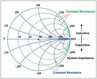
The Smith chart is a tool that maps the complex reflection coefficient (Γ) to the test device's impedance.
In a Smith chart, the rectilinear impedance plane is reshaped to form a circular grid.
With markers, you can readout Real + Imaginary (R + jX) or Magnitude and Phase.
Polar format is used to view the magnitude and phase of the reflection coefficient (G) from your S11 measurement.
In Polar format, Markers display the following:
Linear magnitude (in units)
Phase (in degrees)
In the above image, the dashed circles represent reflection coefficient. The outermost circle represents a reflection coefficient () of 1, or total reflected signal. The center of the circle represents a reflection coefficient () of 0, or no reflected signal.
The radial lines show the phase angle of reflected signal. The right-most position corresponds to zero phase angle, (that is, the reflected signal is at the same phase as the incident signal). Phase differences of 90°, ±180°, and -90° correspond to the top, left-most, and bottom positions on the polar display, respectively.
With markers, you can readout Real + Imaginary (R + jX) or Magnitude and Phase.