How 1-port Measurements are Made |
All 1-port measurements are by definition “reflection” measurements. This means that only one port is used to send a signal AND measure the reflections of that signal.
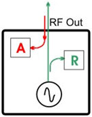
There are three components in the FieldFox which are key to making 1-port reflection measurements:
This image and following explanation shows the RF OUT port of a N9912A. See also Raw Receiver Measurements.
A signal source which sends signal out RF OUT.
A “reference” (R) receiver that is used ONLY to measure the “incident” signal out of the source.
A test port (A) receiver for measuring reflected signals coming back INTO RF OUT.
A transmission system is made up of the transmitter, the transmission cable, the antenna, and all the connectors in between. In an ideal transmission system, all of the signal power that is sent out the transmitter is completely broadcast into the air. However, in reality, as the signal encounters disruptions, such as worn connectors and cable kinks, some of the signal is reflected back toward the transmitter. The amount of reflection is directly proportional to the severity of the disruption. Any reflected signal is wasted energy and results in a weaker signal being broadcast. If the reflections are significant they could cause damage to the transmitter.
The following is a general process for making 1-port reflection measurements:
The FieldFox is connected to the transmission system in place of the transmitter. The FieldFox internal signal source (transmitter) is of much lower power than a transmitter that is used to transmit radio, TV, and cell phone signals.
During the calibration process, the power, frequency, and phase of the FieldFox transmitted signal is VERY accurately known. Adapters or cables that are attached to the FieldFox are measured and their effects are removed from subsequent measurements.
As disruptions in the transmission feed system are encountered, the power and phase of the reflected signal is measured by the FieldFox ‘A’ receiver.
The reflected signals are compared, or ‘ratioed’ to the power and phase of the ‘R’ receiver incident signal that was transmitted.
From this general type of measurement, all of the FieldFox 1-port measurements can be calculated. For example, ‘Fault’ measurements calculate the severity and distance to all disruptions in the transmission system. For more information how the calculation is performed, see http://literature.cdn.keysight.com/litweb/pdf/5989–5723EN.pdf
Also, the loss in the transmission cable can be measured if the end of the transmission line is terminated in a SHORT or OPEN.