Periodic Cable Faults
CAT Mode DTF measures the reflection of incident energy that is caused by imperfections or disturbances (bumps) which are distributed throughout the cable length. These bumps may take the form of a small dent or a change in diameter of the cable. These bumps are caused by periodic effects on the cable while in the manufacturing process. For example, consider a turn-around wheel with a rough spot on a bearing. The rough spot can cause a slight tug for each rotation of the wheel. As the cable is passed around the wheel, a small imperfection can be created periodically corresponding to the tug from the bad bearing.
Each of these small variations within the cable causes a small amount of energy to reflect back to the source due to the non-uniformity of the cable diameter. Each bump reflects so little energy that it is too small to observe with fault location techniques. However, reflections from the individual bumps can sum up and reflect enough energy to be detected as Cable Loss or Return Loss. As the bumps get larger and larger, or as more of them are present, the Cable Loss or Return Loss values will also increase. The energy reflected by these bumps can appear in the loss measurement as a reflection spike at the frequency that corresponds to the spacing of the bumps. The spacing between the bumps is one half the wavelength of the reflection spike. As the sizes of the bumps, their spacing, and the number of bumps vary within the manufacturing process, varying amounts of Cable Loss or Return Loss are observed.
Discrete Cable Faults
In addition to a set of periodic bumps, a cable can also contain one or more discrete faults. For this discussion, discrete imperfections will be referred to as “faults,” and periodic imperfections will be referred to as “bumps.”
Reflections from discrete faults within the cable will also increase the level of reflection that is measured. The energy reflected from a fault will sum with the energy reflected from the individual bumps and provide a higher reflection level.
A fault within the cable will provide the same type of effect as a bad connector. If the fault is present within the end of the cable nearest to the FieldFox, the effect will be noticed throughout the entire frequency range. As the fault is located further into the cable, the cable attenuation will reduce the effect at higher frequencies. The reflected energy travels further through the cable at lower frequencies where the cable attenuation per unit distance is lower.
Cable Problems
The following shows potential problems with transmission cables.
|

|
Bent Cable
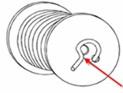
Poor measurement results can occur if the cable is bent or kinked near the end of the spool.
|
|

|
Deformed Cable
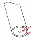
Compressing the dielectric (the gap) will produce egg-shaped or oval deformations which can cause impedance mismatches and affect the quality of the connector Model compensation. This can easily happen when using diagonal cutters to cut the cable.
|
|

|
Contaminated Dielectric
When a cable is cut, contamination of the dielectric can occur from cuttings or shrapnel from the outer or inner conductor. This type of contamination can cause problems and change the connector Model compensation needed.
|
|

|
Damaged Outer Conductor
The outer conductor may be cut or dented when the outer insulation is removed. This can cause a close-in fault.
|
|

|
Non-Flush Cut
Cables which require a flush cut, such as for GTC-XXX-TX-N (“Pogo”) connectors, might not actually be cut in such a way. This can cause an inconsistent connection or poor repeatability of the measurement.
|


