Opt. 006 Define Measurement
This topic describes the measurement dialogs displayed based on the
instrument and fixture.
In this topic:
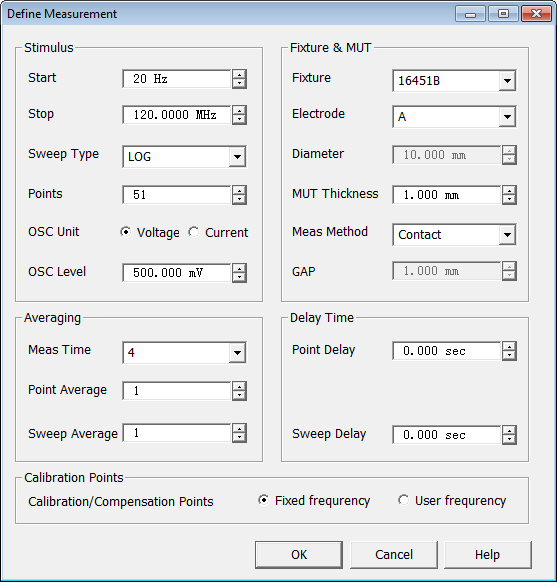
Click Calibration then Define Measurement to display the
Define Measurement dialog.
Impedance Trace Data Types
Fixture |
Impedance
Trace Data Type |
16451B (contact method)
|
Cp and D |
16451B (non-contact method)
|
Cp, D, Cpg, and Dg. Cpg and Dg
are the results when the MUT is not inserted. |
16452A |
Cp, G, C0, and G0. C0 and G0
are the results of air capacitance measurement. |
16454A |
R,
X, MUT_R, and MUT_X. MUT_R and MUT_X are calculated impedance
when ideal one-turn coil is built on the MUT with defined dimension
that has rectangular cross-sectional shape, which is defined as
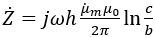
Where,
 is measured
complex permeability value of MUT
is measured
complex permeability value of MUT
b
is inner diameter of MUT
c
is outer diameter of MUT
h is height of MUT |
E4980A/AL with 16451B/16452A
16451B |
16452A |
 |
 |
Stimulus
Start
- Enter the start frequency using the up/down arrows or double-click in
the field to open the numeric keypad.
Stop
- Enter the stop frequency using the up/down arrows or double-click in
the field to open the numeric keypad.
Sweep Type
- Select LOG or LIN
sweep type.
Points
- Enter the number of measurement points using the up/down arrows or double-click
in the field to open the numeric keypad.
OSC Unit
- Set oscillator test signal to voltage or current.
OSC Level
- Set oscillator test signal level using the up/down arrows or double-click
in the field to open the numeric keypad.
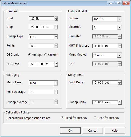
Fixture & MUT
Fixture
- Select the fixture.
16451B
only
Electrode
- Select the fixture electrode.
Electrode
Diameter - Enter the electrode diameter using the up/down arrows
or double-click in the field to open the numeric keypad.
MUT Thickness
- Enter the MUT thickness using the up/down arrows or double-click in
the field to open the numeric keypad.
Meas Method
- Select Contact or Non
Contact measurement method.
GAP
- Distance between upper and lower electrodes.
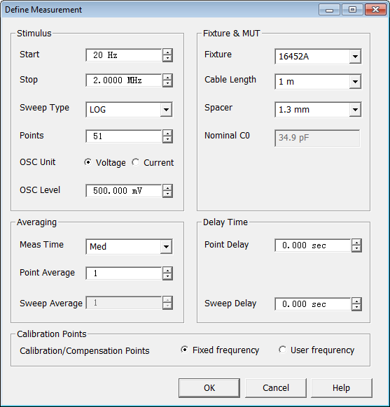
16452A only
Cable Length
- Enter the cable length using the up/down arrows or double-click in the
field to open the numeric keypad.
Spacer
- Enter the spacer width using the up/down arrows or double-click in the
field to open the numeric keypad.
Nominal
C0 - Displays the typical
air capacitance value when measuring the C0 with selected spacer. The
expected value is +/- 10 to 25%. Refer to the 16452A operation and service
manual for details.
Averaging
Meas Time - Select from:
Short - Shortens the measurement
time.
Med - Sets the measurement time
between Short and Long.
Long. - Lengthens the measurement
time.
Point Average
- Sets the number of data points to average using the up/down arrows or
double-click in the field to open the numeric keypad.
Sweep Average
- (Not available on E4980A)
Delay Time
Point Delay
- Sets the time to wait between measurement points using the up/down arrows
or double-click in the field to open the numeric keypad.
Sweep Delay
- Sets the time to wait between measurement sweeps using the up/down arrows
or double-click in the field to open the numeric keypad.
Calibration Points - Select
the type of calibration frequency points to use in obtaining calibration
data.
Fixed frequency
- Obtain calibration/compensation data at fixed frequency points covering
the entire frequency range of the instrument. In measurement, user calibration
or fixture compensation is applied to each measurement point by using
interpolation. Even if the measurement points are changed by altering
the sweep setups, you don't need to retake the calibration/compensation
data.
User frequency
- Obtain calibration/compensation data at the same frequency points as
used in actual measurement, which are determined by the sweep setups.
Each set of calibration/compensation data is applied to each measurement
at the same point. If measurement points are changed by altering the sweep
setups, calibration/compensation data become invalid and calibration/compensation
data acquisition is again required.
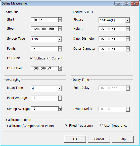
E4990A with 16451B/16452A/16454A
Note: The E4990A
Option 120 using the 42942A adapter is required with the 16454A fixture.
Stimulus
Start
- Enter the start frequency using the up/down arrows or double-click in
the field to open the numeric keypad.
Stop
- Enter the stop frequency using the up/down arrows or double-click in
the field to open the numeric keypad.
Sweep Type
- Select LOG or LIN
sweep type.
Points
- Enter the number of measurement points using the up/down arrows or double-click
in the field to open the numeric keypad.
OSC Unit
- Set oscillator test signal to voltage or current.
OSC Level
- Set oscillator test signal level using the up/down arrows or double-click
in the field to open the numeric keypad.
Fixture & MUT
Fixture
- Select the fixture.
Note:
For the 16454A fixture, a large (16454A(L))
or small (16454A(S)) fixture can
be selected.
16451B
only
Electrode
- Select the fixture electrode.
Diameter
- Enter the MUT diameter using the up/down arrows or double-click in the
field to open the numeric keypad.
MUT Thickness
- Enter the MUT thickness using the up/down arrows or double-click in
the field to open the numeric keypad.
Meas Method
- Select Contact or Non
Contact measurement method.
GAP
- Distance between upper and lower electrodes.
16452A only
Cable Length
- Enter the cable length using the up/down arrows or double-click in the
field to open the numeric keypad.
Spacer
- Enter the spacer width using the up/down arrows or double-click in the
field to open the numeric keypad.
Nominal
C0 - Displays the typical
air capacitance value when measuring the C0 with selected spacer. The
expected value is +/- 10 to 25%. Refer to the 16452A operation and service
manual for details.
16454A only
Note:
You must enter the MUT dimensions before a measurement can be performed. Use a micrometer or calipers to
measure the outer (shown as c in the below figure) and inner (shown as
b in the below figure) diameters and height (shown as h in the below figure).
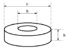
Height
- Enter the height of the MUT using the up/down arrows or double-click
in the field to open the numeric keypad.
Inner Diameter
- Enter the inner diameter of the MUT using the up/down arrows or double-click
in the field to open the numeric keypad.
Outer Diameter
- Enter the outer diameter of the MUT using the up/down arrows or double-click
in the field to open the numeric keypad.
Averaging
Meas Time - Sets measurement time
to 1 (fastest), 2, 3, 4, or 5 (slowest and more precise).
Point Average
- Sets the number of data points to average using the up/down arrows or
double-click in the field to open the numeric keypad.
Sweep Average
- Sets the number of sweeps to average using the up/down arrows or double-click
in the field to open the numeric keypad.
Delay Time
Point Delay
- Sets the time to wait between measurement points using the up/down arrows
or double-click in the field to open the numeric keypad.
Sweep Delay
- Sets the time to wait between measurement sweeps using the up/down arrows
or double-click in the field to open the numeric keypad.
Calibration Points - Select
the type of calibration frequency points to use in obtaining calibration
data.
Fixed frequency
- Obtain calibration/compensation data at fixed frequency points covering
the entire frequency range of the instrument. In measurement, user calibration
or fixture compensation is applied to each measurement point by using
interpolation. Even if the measurement points are changed by altering
the sweep setups, you don't need to retake the calibration/compensation
data.
User frequency
- Obtain calibration/compensation data at the same frequency points as
used in actual measurement, which are determined by the sweep setups.
Each set of calibration/compensation data is applied to each measurement
at the same point. If measurement points are changed by altering the sweep
setups, calibration/compensation data become invalid and calibration/compensation
data acquisition is again required.