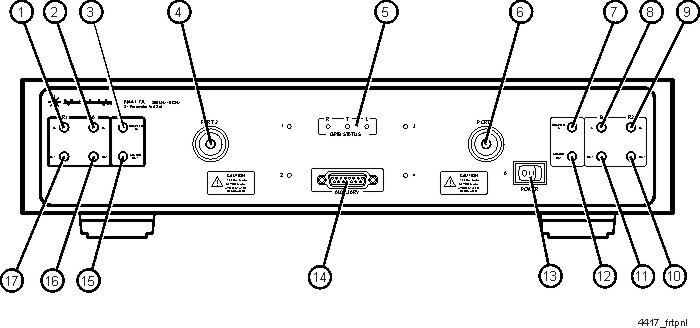
ID Number
Front Panel Feature
Feature Description
1
R1 IN
SMA (f) connector that is connected to the network analyzer R1 IN connector using a semirigid cable.
2
A IN
SMA (f) connector that is connected to the network analyzer A IN connector using a semirigid cable.
3
COUPLER IN
SMA (f) connector that is connected to the network analyzer COUPLER IN connector using a semirigid cable.
4
PORT 2
APC-7 connector that is connected to the DUT or fixture.
(+17 dBm maximum operating level)
5
GPIB STATUS
Three LEDs (R, T, and L) that display the GPIB status of the test set when it is communicating with the network analyzer. R = Remote Operation, T = Talk mode, L = Listen mode.
6
PORT 4
APC-7 connector that is connected to the DUT or fixture.
(+17 dBm maximum operating level)
7
COUPLER IN
SMA (f) connector that is connected to the network analyzer COUPLER IN connector using a semirigid cable.
8
B IN
SMA (f) connector that is connected to the network analyzer B IN connector using a semirigid cable.
9
R2 IN
SMA (f) connector that is connected to the network analyzer R2 IN connector using a semirigid cable. This connector is installed on Option 104 only. It is not installed on Option 103.
10
R2 OUT
SMA (f) connector that is connected to the network analyzer R2 OUT connector using a semirigid cable. This connector is installed on Option 104 only. It is not installed on Option 103.
11
B OUT
SMA (f) connector that is connected to the network analyzer B OUT connector using a semirigid cable.
12
SOURCE OUT
SMA (f) connector that is connected to the network analyzer SOURCE OUT connector using a semirigid cable.
13
POWER
ON/OFF switch that disconnects the mains circuits from the mains supply before other parts of the test set. The front panel POWER switch disconnects the mains circuits from the mains supply after the EMC filters and before other parts of the instrument.
14
AUXILIARY
15-pin ribbon (f) connector that may be connected to the Keysight N4430A/B ECal module to provide ECal capability.
15
SOURCE OUT
SMA (f) connector that is connected to the network analyzer SOURCE OUT connector using a semirigid cable.
16
A OUT
SMA (f) connector that is connected to the network analyzer A OUT connector using a semirigid cable.
17
R1 OUT
SMA (f) connector that is connected to the network analyzer R1 OUT connector using a semirigid cable.