ID Number
Front Panel Feature
Feature Description
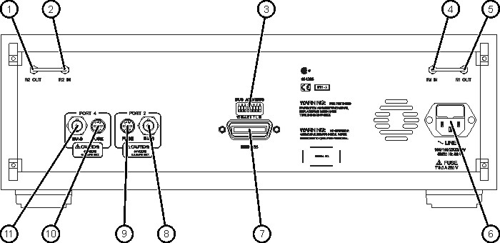
1
R1 OUT
2.4 mm (f) connector that connects to the network analyzer REFERENCE 1 OUT connector using a semirigid cable.
2
R1 IN
2.4 mm (f) connector that connects to the network analyzer REFERENCE 1 RCVR R1 connector using a semirigid cable.
3
PORT 2
2.4 mm bulkhead test port connector that is connect to the DUT or fixture. (+17 dBm maximum operating level)
4
GPIB STATUS
Three LEDs (R, T, and L) that display the GPIB status of the test set when it is communicating with the network analyzer. R = Remote Operation, T = Talk mode, L = Listen mode.
5
PORT 4
2.4 mm bulkhead test port connector that is connect to the DUT or fixture. (+17 dBm maximum operating level)
6
R2 IN
2.4 mm (f) connector that connects to the network analyzer REFERENCE 2 RCVR R2 connector using a semirigid cable.
7
R2 OUT
2.4 mm (f) connector that connects to the network analyzer REFERENCE 2 OUT connector using a semirigid cable.
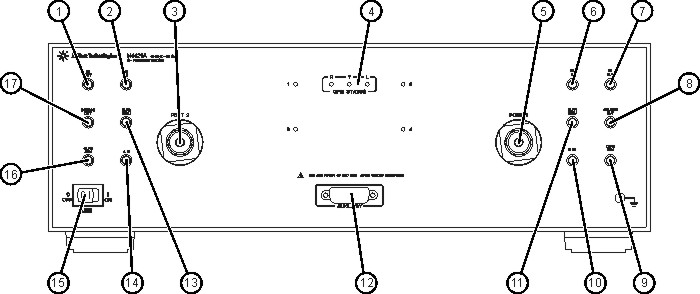
8
SOURCE OUT
2.4 mm (f) connector that connects to the network analyzer PORT 2 SOURCE OUT connector using a semirigid cable.
9
CPLR ARM
2.4 mm (f) connector that connects to the network analyzer PORT 2 CPLR ARM connector using a semirigid cable.
10
B IN
2.4 mm (f) connector that connects to the network analyzer PORT 2 B IN connector using a semirigid cable.
11
CPLR THRU
2.4 mm (f) connector that connects to the network analyzer PORT 2 CPLR THRU connector using a semirigid cable.
12
AUXILIARY
15-pin ribbon (f) connector. Not currently used.
13
CPLR THRU
2.4 mm (f) connector that connects to the network analyzer PORT 1 CPLR THRU connector using a semirigid cable.
14
A IN
2.4 mm (f) connector that connects to the network analyzer PORT 1 A IN connector using a semirigid cable.
15
LINE
ON/OFF switch that disconnects the mains circuits from the mains supply before other parts of the test set. The front panel POWER switch disconnects the mains circuits from the mains supply after the EMC filters and before other parts of the instrument.
16
CPLR ARM
2.4 mm (f) connector that connects to the network analyzer PORT 1 CPLR ARM connector using a semirigid cable.
17
SOURCE OUT
2.4 mm (f) connector that connects to the network analyzer PORT 1 SOURCE OUT connector using a semirigid cable.