Channel Loss Compensation

Overview

Time domain reflectometry (TDR) is a powerful tool to locate discontinuities on transmission lines. However, loss and dispersion of the transmission lines deteriorate sharpness of peaks and make it difficult to locate the discontinuities.

The Channel Loss Compensation feature invokes an algorithm which compensates the loss and the dispersion of the transmission lines for TDR to reproduce sharp peaks at the discontinuities.


Channel Loss Compensation Dialog


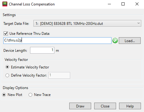
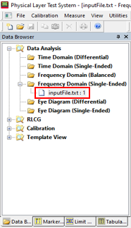
Target Data File - Select the target file using the drop down menu.

Note: The Channel Loss Compensation calculates loss by either using the measured reference thru data as input or by estimating the thru data from the target DUT data.

Use Reference Thru Data - Check to use reference thru data selected using the Load... button.

Load... button - Loads a reference thru data file.

Device Length - Sets the device length.

Estimate Velocity Factor - Select for estimating velocity factor.

Define Velocity Factor - Select to use and enter a constant velocity factor between 0 and 1.

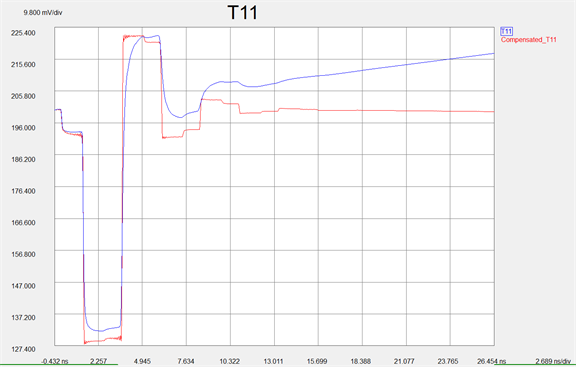
New Plot - Adds a new plot.

New Trace - Adds a new trace.

Draw button - Draws a new plot or a new trace.


How to do channel loss compensation

  1. Open a file in single-ended or differential frequency (time) domain, and open a reference thru file if needed.
  2. Click Tools, then Channel Loss Compensation.
  3. In the Channel Loss Compensation dialog, specify the input files, device length, and velocity factor, then click the Draw button to add a new plot or trace with the compensated data (red trace below).