Non-insertable calibrations are those in which the test port connectors are of the same gender (male-to-male or female-to-female). For non-insertable calibrations, the thru adapter to be used must be characterized by itself so that its effects can later be removed from the calibration measurement results. Learn more about calibration THRU methods.
Several standard thru adapter characterization files have been provided with PLTS (see the ../PLTS/adapters directory) and are automatically selected based on the calibration kit to be used. These files may be used with very good results, but for the very highest accuracy, it is recommended that you characterize your own adapters using the following procedure.
To perform the characterization, first, a short/open/load calibration is performed directly at the front panel of the system. Either one or two test ports will be used depending on the adapter category selected during the process. Then the adapter is inserted and the short/open/load calibration is repeated. The resulting adapter S-parameters are saved in Citifile format, which can later be de-embedded from the device measurement.
For adapters that will be used for broadband measurements, characterize the adapter over the entire frequency range of the instrument with as many points as possible. This allows for interpolation of adapter data if the frequency points used in a later DUT measurement are not exactly the same as the adapter frequency points.
Adapter characterization is performed directly at the instrument front panel (either Port 1 or Ports 1 and 4). If an additional adapter is needed between the front panel and the adapter to be characterized (for type or gender change), install the additional adapter first (metrology grade recommended), and perform all calibrations with it installed.
For purposes of characterization, your adapters must have an orientation. Mark the connectors on the adapter as ports 1 and 2, and treat them as such during the characterization procedure. Forward orientation has the lower-numbered adapter port connected to the test-set port.
Follow these steps to characterize your adapters:
1. Click Utilities, then Characterize Adapter
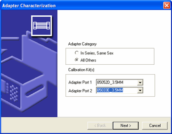
2. Select the appropriate Adapter Category and the Calibration Kit to be used. The two adapter characterization categories are:
"In-Series, Same-Sex" uses a single port (Port 1) and applies only to adapters having the same type and gender on both ends (3.5 mm male-to-male, for example). Select the calibration kit to be used on Port 1 from the pull-down menu.
"All Others" uses two ports (Ports 1 and 2) and allows the adapter types to be specified independently. Select the calibration kits to be used on Port 1 and on Port 2 from the pull-down menus.
Click Next > to continue.
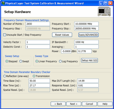
3. Set up the stimulus to measure the adapter in the Adapter Characterization wizard's Calibrate Hardware for Measurement window. When you are finished, click the Next > button to continue.
Refer to Setup Hardware Dialog for information on this window's parameters.
4. Connect one of the standards (Short - Open - Load) to Port 1 on the PLTS and click the icon that represents the standard in the Port 1 Ref area. The PLTS will measure the adapter and when it has finished, the icon color changes from red to green.

Each of the three icons represents a different calibration standard.
![]() represents the short standard
represents the short standard
![]() represents the open standard
represents the open standard
![]() represents the 50-ohm load standard
represents the 50-ohm load standard
5. Repeat step 4 for the two remaining icons. The color of all three icons in the Port 1 Ref area have changed from red to green.
6. Connect the adapter that is being characterized to Port 1. Mark the end that is connected to Port 1. The opposite end will be connected to Port 4 later in this procedure.
7. Repeat step 4 and step 5 - connecting the standards to the adapter. Click the icons in the Port 1 FWD area to make the measurements. As before, as each standard is measured, the color of the icon changes from red to green. When you have finished, the color of all three icons in the Port 1 FWD should have changed from red to green.
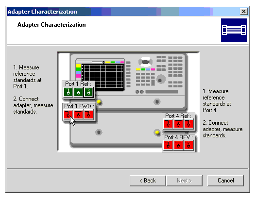
8. When the standards have been measured on the adapter at Port 1 and all of the Port 1 standard icon colors have changed from red to green, repeat step 4 through step 7 on Port 4. As mentioned in step 6, remember to connect opposite end of the adapter to Port 4 (the adapter end that you did not connect to Port 1).
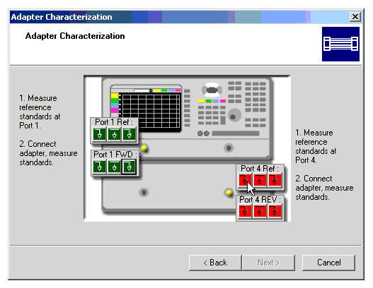
9. When you have finished, click the Next > button to continue. All 12 standard icon colors have changed from red to green.
10. When the characterization is complete, save the adapter file. Enter a file name for the adapter data and click Finish. The file is automatically saved as a ".txs" file. The default directory for saving adapter characterization information is C:/Program Files/Keysight/PLTS/adapters, where C is the hard drive where the PLTS is stored. 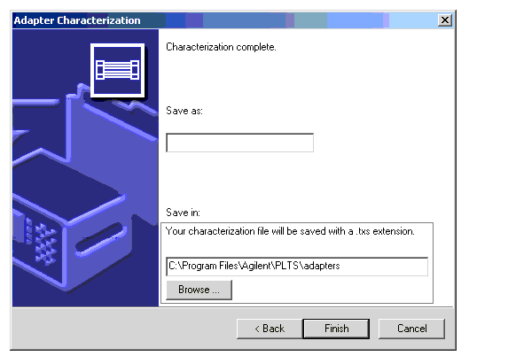
11. Since the characterization file is in Citifile format, you can import the data and make a visual check of the quality of the characterization. Select Import from the File menu and then select Citifile. You may open and inspect the adapter characterization file.