As data rate for digital systems continue to increase, ensuring good signal integrity performance of PCB is becoming more important. Channel loss is one of the important parameters to measure in order to meet the requirements of signal integrity of high speed I/O. Selecting the right PCB material is important to avoid costly overdesign, or risk of facing performance issues. An accurate and efficient PCB channel loss measurement methodology is important for system designer or PCB manufacturers
Due to the increase in I/O speed, existing IPC time-domain test methods in IPC-TM-650 method 2.5.5.12 is no longer adequate to address the quality of PCB loss measurements for high-speed applications. Intel Data Center Group (DCG) SI team first introduced the Delta-L+ approach to close the gap. It has been widely adopted across the industry. Most of the works have been adopted in IPC test method 2.5.5.14.
We provide Delta-L 4.0 1L/2L/3L measurement solution:
You can use Keysight ENA/PNA to test multiple lines to get the s4p files, and use Delta-L feature in PLTS to get the Delta-L results.
Input - Click Browse... to load a touchstone (*.s4p) file or select from previously loaded files in the list box “Available Files”. Port Order - Use the drop-down menu to select a port order. Trace Length - Enter the trace length in feet, inches, or millimeters. Available Files - Files which are open in PLTS but not selected as Delta-L input. Selected Files - Files which are selected as Delta-L input. Calculate - Displays the Delta-L resultant traces. |

Input - Click Browse... to load a touchstone (*.s4p) file. Use the drop-down menu to select from previously loaded files. Port Order - Use the drop-down menu to select a port order. Trace Length - Enter the trace length in feet, inches, or millimeters. The suggested trace lengths are: X2 ³ 4 inch, X1-X2 ³ 4 inc Enhance Mode - If there is glitch in the input data due to measurement error, enhance mode can be enabled to avoid glitches in the final result. Iteration Point - A smoothing algorithm is used in the enhance mode, and the iteration point determines the smoothing point. Calculate - Displays the Delta-L resultant traces. |
Input - Click Browse... to load a touchstone (*.s4p) file. Use the drop-down menu to select from previously loaded files. Port Order - Use the drop-down menu to select a port order. Trace Length - Enter the trace length in feet, inches, or millimeters. The suggested trace lengths are: X2 ³ 4 inch, X1-X2 ³ 4 inc Enhance Mode - If there is glitch in the input data due to measurement error, enhance mode can be enabled to avoid glitches in the final result. Iteration Point - A smoothing algorithm is used in the enhance mode, and the iteration point determines the smoothing point. Calculate - Displays the Delta-L resultant traces. |
Click Utilities, then Delta-L.
Click Browse... to load two touchstone files as inputs. The SDD21 parameters will be previewed in a template view.

For two-line and three-line methods, set the Port Order, Trace Length and Enhance Mode. The suggested trace lengths are: X2 ³ 4 inches, X1-X2 ³ 4 inches.
Note: If there is a glitch in the input data due to measurement error, enhance mode can be enabled to avoid glitches in the final result. A smoothing algorithm is used in the enhance mode, and the iteration point determines the smoothing point.
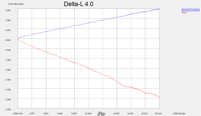
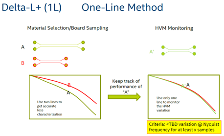
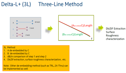
Click Calculate. The Delta-L result will be displayed in one or more plots. In one-line method, the mean value and standard deviation of the insertion loss of unit length will be shown. In two-line and three-line methods, the eigen value, curve fitted and uncertainty data will be shown, the meanings of which are as described below.
Eigen Value represents the raw de-embedded insertion loss curve, which is often plagued with oscillations and aberrations due to various sources of measurement and de-embedding error.
Curve Fitted represents the corrected data in order to report the true loss performance of the device under test.
Uncertainty is a quantitative indicator of measurement quality. With the estimated uncertainty, the user can quickly decide whether he/she would like to accept or reject the measurement result. Furthermore, the user can easily identify "suspicious" cases from a large amount of insertion loss measurement data to further investigate the root cause of low-quality measurement (e.g. a bad connection or bad probe landing).