
The dielectric substrate and conductor surface roughness (SR) characteristics of printed circuit boards (PCBs) are important in high-speed interconnect designs. The direct usage of these material property values from their respective manufacturers’ data sheets into simulation often results in poor match between measurement and simulation.
PLTS introduces the new PCB material characterization feature to address this issue. It employs a 2-D stripline simulator together with the wideband dielectric model and surface roughness (SR) models, tuning the model parameters until a good correlation between simulation and measurement is achieved. Then the material property values (DK, DF, SR) are extracted. The Svensson-Djordjevic model is used as the dielectric model. The surface roughness models are the Huray model and the Cannonball model. Users can also specify the conductor surface to be smooth so that the surface roughness estimation is skipped.
This feature requires PLTS option N19308B PCB Material Characterization and PLTS base option N19301B.
To use this new feature, click the PCB Material Characterization item under the Utilities menu in PLTS. The PCB Material Characterization pane shows up. There are many configurations on it. Please see the details below.
Trace Type: Choose either Single-Ended or Differential. Only single-ended or differential striplines are supported.
Calculated From: Choose either 2-Line or DUT. If 2-Line is chosen, the SNP file paths of a long trace and a short trace need to be provided in the following Long Trace and Short Trace textboxes. PLTS de-embeds the short trace from the long trace to get the DUT trace data and extracts the material property values from the DUT trace data. If DUT is selected, the SNP file path of the DUT trace data is provided directly by the user.
Long Trace: The SNP file path of the long trace.
Short Trace: The SNP file path of the short trace.
DUT: The SNP file path of the DUT trace data.
Port Order: Choose either 1→2, 3→4, …, 2N-1→2N or 1→3, 2→4, …, N→2N.
Truncation Frequency: If Truncation Frequency is less than the stop frequency of the user SNP data, PLTS discards the data above Truncation Frequency.
DUT Length: The difference in length between the long and short traces.
Use PCB Stack-Up in Calculation: If Use PCB Stack-Up in Calculation is chosen, PLTS employs the stack-up settings in its calculation and accurate DK, DF, SR values can be extracted. If Use PCB Stack-Up in Calculation is NOT chosen, rough DK, DF values are extracted, and no SR value is calculated.
Trace Top Width (Wt): The width of the signal conductor’s top surface.
Trace Bottom Width (Wb): The width of the signal conductor’s bottom surface.
Etch Factor: EtchFactor = (TraceBottomWidth-TraceTopWidth)/(2*TraceThickness).
Trace Thickness (T): Thickness of the signal conductor.
Trace Spacing (S): The distance between the two signal conductors. It’s only applied to the differential case.
Top Height (Ht): The distance from the top surface of the signal conductor to the top ground plane.
Bottom Height (Hb): The distance from the bottom surface of the signal conductor to the bottom ground plane.
Conductivity: The metal conductivity of the signal conductor in Siemens per meter (S/m).
Click the Calculate button to start the material characterization calculation. It would take a while to finish. The Advanced button launches the PCB Material Characterization – Advanced dialog.
This dialog allows a user to edit the model parameters. PLTS supports the Svensson-Djordjevic model for the dielectric substrate and the Huray model for the conductor surface roughness. The Cannonball model, a variant of the Huray model, is also supported.

This model only needs four variables to describe the wide-band DK/DF:
 ,
,  ,
, , and
, and 
is the low frequency of interest
is the high frequency of interest
and
are user-defined model parameters

From the equation (1), it’s easy to see that if DK and DF at certain
reference frequency are known,
and can be determined.

In PLTS, Low Frequency, High Frequency and Reference Frequency are user-defined model parameters. The Reference DK and Reference DF at the Reference Frequency are to be estimated by the software.
The conductor surface is divided into hexagonal tiles, and each tile is piled into a pyramid shape with same number of equal-sized balls. The Huray correction factor is defined as:
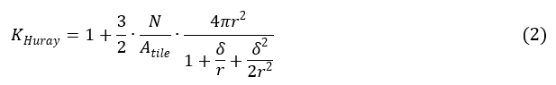
N is the number of balls in area Atile
Atile is the area of ball count, which is the area of the tile
r is the effective ball radius
δ is the skin depth
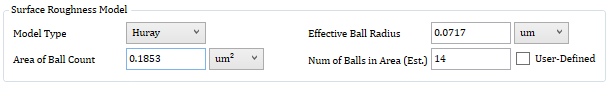
In PLTS, the Effective Ball Radius and Area of Ball Count are user-defined model parameters. Num of Balls in Area is to be estimated. If User-Defined is checked, Num of Balls in Area will also be user-defined. The software will then use this user-defined value and doesn’t estimate it anymore.
This is a special form of the Huray model. It assumes that the number of equal-sized balls is always 14. The area of ball count can be derived from the effective ball radius.
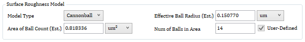
In PLTS, The Num of Balls in Area is fixed to be 14. The Effective Ball Radius and Area of Ball Count are to be estimated by the software.
On this dialog, there are some other useful settings. Please see the description below.
Export Data To: Export the frequency-dependent DK/DF values and the SR values into a CSV file.
Show Calculated S-Parameters: Display the simulation S21 or SDD21 in the same plot as the measurement S21 or SDD21.
Save Settings: Save all the settings into an XML file, including the settings on the PCB Material Characterization Pane.
Recall Settings: Recall all the settings from the XML file saved previously.
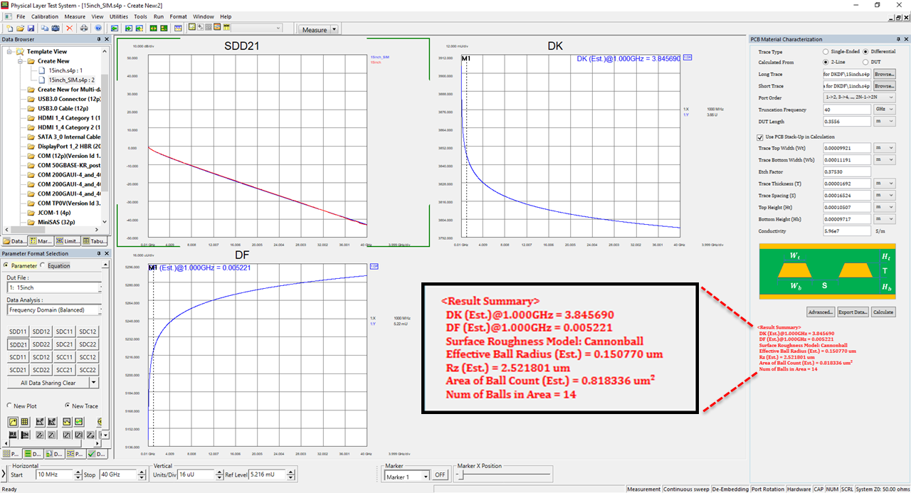
Result Summary: It’s displayed at the bottom of the setting pane. It shows the estimated DK and DF values at the reference frequency, the surface roughness model in use and its parameters both estimated and user-defined.
SDD21 Traces (S21 for the single-ended case): The first trace is the simulation SDD21 (S21). The second trace is the measurement SDD21 (S21).
DK Trace: The curve of DK vs frequency is plotted.
DF Trace: The curve of DF vs frequency is plotted.
Click the Export Data button: User can export the frequency-dependent DK/DF values and the SR values into a CSV file.
9-Jan-2024 |
New topic. |