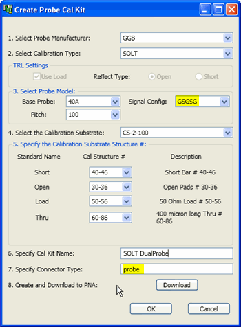
This dialog simplifies the setup of the Probe and ISS (Impedance Standard Substrate) specifications to be used when performing a calibration with a Cascade or GGB probe station.
From the PNA Cal Wizard – Define Cal Settings dialog, click Create Probe Cal Kit

|
This dialog appears when you click Set Probe Config on the Define Calibration Settings dialog. To edit this Cal Kit after it is created, use the Advanced Modify Cal Kit feature in the PNA. 1. Select Probe Manufacturer: Select from Cascade and GGB. 2. Select Calibration Type Choose from:
TRL Settings - Reflect Type: Available when Cal Type is TRL and LRM. Use Load - Check when using a Load standard as a very long Line standard to cover the lower frequencies. The TRL line length is often calculated from 0.25 * wavelength at center frequency of the entire span. Select either Open or Short for the type of reflection standard. Only one can be selected. 3. Select Probe ModelNote: If your probe model and other selections are not available in the following settings, this means that PLTS does not have the appropriate ISS files. These must be obtained from the manufacturer of the probe (Cascade). Base Probe Select from the list provided to populate other settings. Select <Generic> if your probe model does not appear on the list. Option Select from the list provided.. Select <blank> if not applicable or if your probe option does not appear on the list. Signal Config Select from the list the appropriate 'ground/signal' footprint for your probe. Pitch Select from the list provided.
4. Select Calibration Substrate Select the ISS that you will be using to perform the calibration.5. Specify the Calibration Substrate Structure #: Select the Structure Type ID that you will be using as each standard during the calibration. Show Line Ranges For TRL calibrations, PLTS calculates the default frequency ranges from the delay of the lines. Click to launch and edit the Line Frequency Settings dialog. 6. Specify Cal Kit Name: Type a name for your new probe Cal Kit as it will appear in the PNA. 7. Specify Connector Type Enter a connector type for the Cal Kit. If a new connector type is used, it will appear in the Connector List. It must be selected on the connector list for it to appear for subsequent calibrations. 8. Create and Download to PNA Click to save the Probe Cal Kit definition to the PNA. After saving, the connector type and cal kit appear in the current instance of the Define Calibration Settings dialog. To edit this Cal Kit after it is created, use the Advanced Modify Cal Kit feature in the PNA. |
|
Line Frequency Settings dialog |
|
To see this dialog, click Show Line Ranges on the Create Probe Cal Kit dialog. Each Line standard is designed to cover a specific frequency range. Review the lines and frequency ranges to be sue that they will cover the measurement of your DUT. |