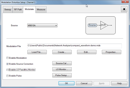
Note: The calibration information is saved in the source modulation .mdx file and is enabled/disabled by the Source Modulation Correction ON/OFF selection.
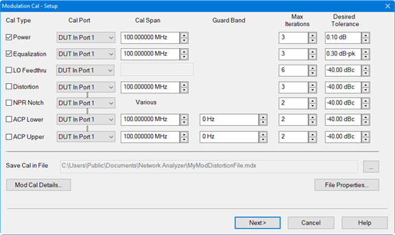
Cal Type - Select the type of calibration to perform:
Power calibrates the total output power of the carrier integrated over the signal span.
Equalization performs a linear pre-distortion calibration which equalizes the magnitude of the modulated signal. The Cal Span defaults to the occupied BW of the Carrier Signal.
LO Feedthru minimizes the LO feedthru tone. (LO feedthru tone may be changed after calibration. LO Feedthru Monitor allows you to check the LO feedthru at every measurement)
Note: LO Feedthru cal is always disabled for internal sources since they use digital up-conversion.
Distortion minimizes the vector error of the modulation signal over the Cal Span. The Cal Span defaults to the occupied BW of the Carrier Signal.
Note: An Equalization calibration is included when a Distortion calibration is performed.
NPR Notch nulls the NPR notch. The Cal Span defaults to the frequency range of the notch. If there are multiple notches having different spans, then Cal Span displays Various.
ACP Upper/ACP Lower nulls the ACP upper/lower sideband of the signal. The Cal Span is set to the frequency width of the ACP sideband being calibrated. The default Cal Span is equal to the carrier span.
Note: The Cal Span may be set so high that the source cannot correct the signal. In this case, the Cal Span will be reduced automatically. The maximum span is 80% of the source sampling frequency.
Cal Port - Selects the calibration plane used for the calibration.
Note: The Cal Port selections for Distortion, NPR, and ACP are coupled. Changing one selection will change them all.
Cal Span - Sets the span of the calibration.
Guard Band - (ACP Cal only) Sets the frequency delta from the edge of the carrier to the beginning of the Cal Span. The default is set to zero. This value is positive for both ACP Lower and ACP Upper.
Note: The Guard Band may be set so high that the source cannot correct the signal. In this case, the Cal Span will be reduced automatically. In addition, it is possible to set the Guard Band so high that the Cal Span is set to zero, in which case the Guard Band will also be limited automatically.
Max Iterations - The calibration routine uses successive approximation. This value sets the maximum number of iterations used by the calibration routine.
Desired Tolerance - Sets the desired tolerance for each calibration.
Save Cal in File - Saves the modulation calibration to a file.
Mod Cal Details... button - Opens the Mod Cal Details dialog.
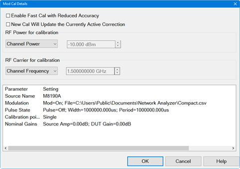
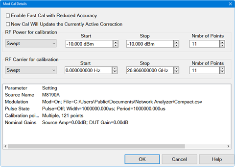
Enable Fast Cal with Reduced Accuracy - Check to perform a faster calibration.
New Cal Will Update the Currently Active Correction - Check to retain the currently active correction data but update those parts that are calibrated by the calibration process with new correction data. For example, if a power calibration is performed after a power and distortion calibration, only the power data will be updated while retaining the distortion correction data.
Fixed - Calibration is performed at a fixed power level.
Cal Power - Sets the fixed power level.
Swept - Calibration is performed at multiple power levels.
Start Sets the beginning value of the power sweep.
Stop Sets the end value of the power sweep.
Nmbr of Points Sets the number of power points to calibrate during a sweep.
Channel Power - Displays either the fixed power or swept power.
RF Carrier for calibration:
Fixed - Calibration is performed at a fixed frequency.
Cal Frequency - Sets the fixed frequency.
Swept - Calibration is performed at multiple frequencies.
Start Sets the beginning frequency value.
Stop Sets the end frequency value.
Nmbr of Points - Sets the number of frequency points to calibrate during a sweep.
Channel Frequency - Displays either the fixed frequency or swept frequency.
Note: Several powers and several frequencies can be set up and the VNA will calibrate all combinations.
VNA Status - Displays a list of parameters and their settings.
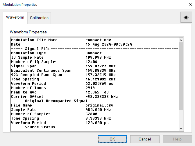
Waveform Tab
Displays the properties of the currently active modulation file, which was selected in the Modulation settings dialog. This information cannot be edited.
Calibration Tab
The Calibration tab displays the calibration files and their properties stored in the .mdx file. Each calibration displayed in the list is for one power level. Calibrations may have been performed on multiple power levels during a single calibration. In this case, multiple calibrations will be saved in the .mdx file. Any of these calibrations can be deleted by selecting the calibration name then clicking on the Delete Cal button.
Next> button- When pressed, the wizard checks to see if the selected filename contains an existing cal file. If it does, then the following warning message is displayed:
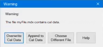
Overwrite Cal Data - Existing cal data will be overwritten.
Append to Cal Data - Keeps all existing cal data and appends only the data for the currently selected Cal Type. For example, if LO Feedthru is selected as the only Cal Type in the Modulation Cal - Setup dialog and the calibration is performed, only the LO Feedthru cal data will be updated and the cal data for all previous cals will remain unchanged. If you repeat the LO Feedthru calibration, and append to the file, it will replace the LO Feedthru cal while leaving the other calibrations (distortion, equalization, NPR, and ACPR) unchanged
Choose Different File - Allows selection of a different cal file.
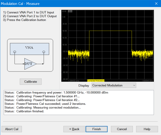
Accesses the Modulation Cal - Measure dialog:
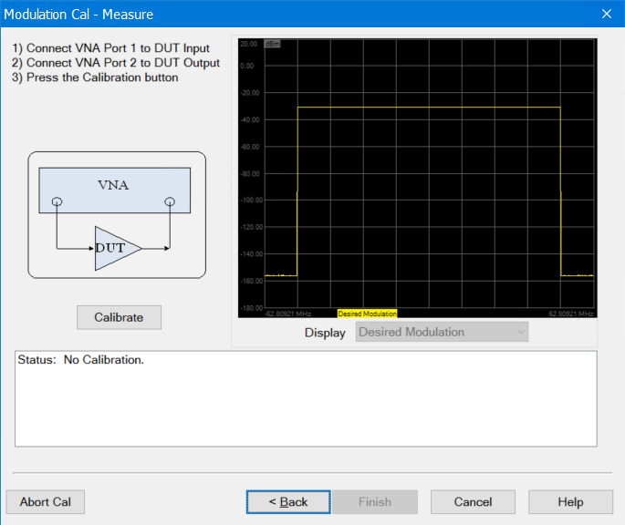
Calibrate button - Starts the calibration.
Display - Select to display one of the following:
Desired Modulation is the ideal simulated signal from the modulation file data.
Uncorrected Modulation is the real-time measured signal without correction.
Corrected Modulation is the real-time measured signal with correction.
Correction Terms displays a static trace showing the correction terms applied to the modulation data.
Calibration Iterations displays multiple static traces used during the calibration.
If one or more of the default tolerance values could not be achieved, a warning message is displayed. You have the option to change the tolerance values and re-calibrate or save the current calibration.


