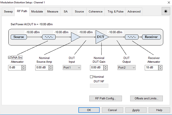
If the Modulation Distortion Setup dialog is not displayed, press Freq> SA Frequency > MOD Setup....
The Sweep, RF Path, Modulate, or Measure tab functions can now be selected.
Select the RF Path
tab.

To change the attenuation in the source path, check Include under the VNA Source Attenuator then use either up/down arrows or double-click in the data entry field and enter the attenuation using the displayed keypad. The source power level to the input of the attenuator will be adjusted based on the attenuation value to ensure the power level specified in the Sweep tab is provided at either the DUT In or DUT Out.
The Nominal Source Amp sets the nominal gain (positive number) from an amplifier, or loss (negative number) due to an attenuation, cable loss, etc. This function provides a method of compensating port power for added attenuation or amplification in the source path. This value is used by the Set Power At function, receiver leveling, and calibration. This value is equal to the Power Offset setting found on the Offsets and Limits dialog. For purposes of this example, assume there is no external source amplifier or attenuation. Since there is no need to account for gain or loss, the value should be set to 0 dB.
Select the DUT Input using the drop down menu then select the VNA port number connected to the DUT input.
Set the nominal DUT gain by clicking in the Nominal DUT Gain data entry field then using either the up/down arrows or double-clicking in the data entry field and entering the gain using the displayed keypad. This value is used by Set Power At DUT Out, receiver leveling, and calibration. This function is also displayed on the calibration dialog.
Select the DUT Output using the drop down menu then select the VNA port number connected to the DUT output.
To change the receiver attenuation, under Receiver Attenuator use either the up/down arrows or double-click in the data entry field and enter the attenuation using the displayed keypad.
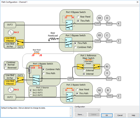
Click
on the Path Configuration...
button and ensure that the correct RF path is selected according to
the Hardware Setup then click OK.
For this example, the Combiner path for Port 1 is selected since the
modulated signal is connected to the rear-panel J10 connector.

Click on the Apply button to apply the setting changes made in this dialog.